|
Fokker D.VIIF (Late)
by Robert
Baumgartner
 |
|
Fokker D.VIIF (late) |

Roden's 1/72 scale Fokker D.VIIF (late) is available online from Squadron.com
The Fokker D.VII was the winner of the first fighter competition
at Adlershof airfield in January 1918. As a result of this, large contracts were
issued for the production of this aircraft. Ironically Albatros, who was Fokkers
main rival, was ordered to produce the D.VII under license.
The Fokker D.VII possessed cantilever wings and welded steel tube construction.
It was powered initially by the 160h.p. Mercedes D III engine before later using
the more powerful 185h.p. BMW engine.
The aircraft was very manoeuvrable and its ability to keep its responsiveness at
altitude when other aircraft would potentially stall endeared the D.VII to
both novice and experienced pilots alike.
|
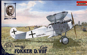
Roden's Fokker D.VII
(late) Kit |
Roden 1/72 Scale Fokker D.VIIF
(late)
Kit No Ro 031
 The
kit consists of 4 sprues of grey coloured plastic, which translate into 61
parts. Not all of these are used and the spare parts box will benefit greatly.
All parts are moulded in a soft plastic and some exhibit flash which is easily
removed. The
kit consists of 4 sprues of grey coloured plastic, which translate into 61
parts. Not all of these are used and the spare parts box will benefit greatly.
All parts are moulded in a soft plastic and some exhibit flash which is easily
removed.
The wings have subtle rib detail and excellent accuracy in outline. The trailing
edges will need a little sanding to get a really fine edge but more of a
surprise is the moulding flaw that appears on the lower wing. A similar one is
also present on the top wing. Luckily, careful sanding will eradicate these
completely. The top wing shows the correct taper and some light bending of the
wing will remove the dihedral that has occurred due to warpage.
The fuselage halves are applicable to the late Fokker product and all doors and
louvers are present. The outline is again very good, with only the overlong
fuselage length needing a couple of millimetres taken off. The exterior shows
the faint indication of the interior structure, which works out quite well under
a coat of paint.
Two styles of radiator are supplied; one with central and one with offset filler
cap.
The aforementioned moulding flaws affect these parts too except that here they
are more difficult to hide as they are on the grill.
Both types of axial fairing are present and both are well short of the required
span.
Fortunately, the undercarriage strut location points are the correct width
apart. Thus, the gluing of an equal amount of the correct thickness of plastic
on each end will fix this problem. Coincidently, the Roden sprue nameplate is of
the right thickness for each end!
Sprue Z is a gem in that it supplies both BMW and Mercedes engines, as well as
Spandaus and, of all things, Parabellums with drums! A taste of things to come?
Before anything else, the main components were test-fitted. The
lower wing was found to be a very poor fit with the joined fuselage halves. The
fuselage halves were therefore thinned until the correct cross-section was
achieved and the bottom wing fitted snugly.
It was now time for the interior. Roden supply the floor, seat, rudder bar,
compass, and control column with associated throttle (OAW two handled type).
Modellers can chose whether to add more, such as cross bracing, control wires,
pump, etc. I chose to scratch build the interior as moulding limitations meant
that some of the supplied items are over scale and the seatbelts came from the
spares box.
Before the fuselage halves are joined, the engine must be installed. This is a
lovely moulding and fitted quite well with only minor adjustments. The top
decking, which ingeniously includes the tachometer and instrument panel, is too
short. It does not span the gap from cockpit to engine bay and thus needs some
amendment.
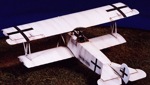
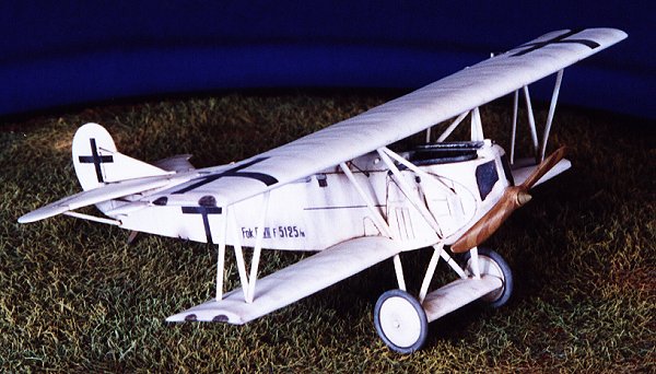
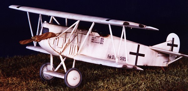
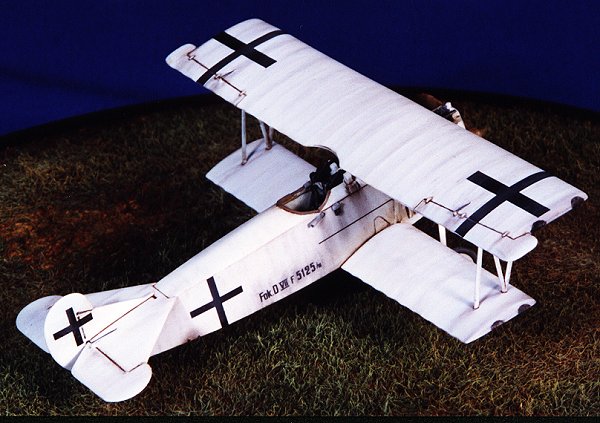
As I chose to model Goring’s all white 5125/17, I installed the radiator with
the centrally mounted filler cap. This is correctly shown in the instructions
and is backed up by the photo in the Squad/Signal Fokker D.VII book. This part
required some careful filling and sanding to ensure a good fit. Due to an
injury, Goring had the port side of his cockpit cut away to allow easy access in
and out of his cockpit. This was replicated using the aforementioned photo as a
guide as well as adding the handgrip.
The lower wing and tailplane were attached after accentuating the elevator hinge
line. While I was at it, the aileron hinge lines were also enhanced. The fin and
rudder was attached next and its good to see that Roden have done their homework
as they allow for the fin to be offset. The control horns on some of these items
were replaced with thin card because the originals were short moulded.
The beautifully detailed machine guns can be added next but they will sit too
high if no correction is made to the ammunition guide/cartridge chutes.
After drilling out the location holes, the struts can be installed. These struts
are very thin and as a consequence, easy to break. You are guaranteed to beak
each one at least once in the cleaning up stage!
The exhaust was installed next but here we have a problem. Although the pipes
line up with the engine correctly, it now becomes apparent that the spacing of
the pipes is not correct. This means that the exhaust does not fit in the engine
panel cut out. Nor does the end of the exhaust fit properly between the struts.
What results is major surgery to the exhaust as well as the port upper cowling.
None of this is overly taxing, just time consuming.
Assembly of the undercarriage and top wing is a breeze. There was no problem
lining up these items once the location points were re drilled.
Goring’s machine also carried an airscrew spinner and this is faithfully
supplied.
Final additions included the flare rack on the starboard fuselage and also the
tube under the cockpit through which the gun is fired. These are correctly
portrayed in the excellent box art. Those seeking reassurance can see these
features in a photo in the Vintage Warbirds series “German Aces of WW1”.
Five schemes are provided for in the kit.
-
Fokker D.VIIF, Ukranainian Peoples
Republic, First Aviation Regiment, Vinnitsa, August 1919.
-
Fokker D.VIIF, Netherlands
Marineluchtvaardienst, 1919-1920.
-
Fokker D.VIIF, Red Army Air force,
Petrograd Military District, Komendantskoye airfield, 1922.
-
Fokker D.VIIF, Lithuanian Air force,
Kaunas, November 1920.
-
Fokker D.VIIF 5125/18, Hermann Goring,
JG 1, October 1918.
Wanting to do a German subject, I
chose Goring’s entirely white machine.
The only two photos I have seen of this machine, show a very clean aircraft. To
model the aircraft in this state would result in a toy-like appearance. For this
reason, it was decided to weather his machine as if it had seen slightly more
service than these publicity shots show.
My example of Roden’s decal sheet was in perfect register. The carrier film was
commendably thin, and presented a matt finish. The sheet is very comprehensive
and includes datum lines, wing stencils, and prop logos.
I have always been suspicious of decals with a matt carrier film, and my worst
fears were realised. After application of the weight table and serial number,
the decals silvered. They were applied to a perfectly glossy surface and the
appropriate decal solutions applied. The aircrafts crosses were then added in
the same way except using strips of black decal from another manufacture. These
showed no silvering at all. A test of the other decals on Rodens sheet on some
scrap plastic covered with gloss paint also silvered.
Note also that the fin/rudder cross supplied for Goring’s machine is too narrow.
This is not an easy kit to build but
once you get past the completion of the fuselage and lower wing the rest
proceeds quickly. I hope that the problem with the decals is confined to my
example only, but would suggest that spare decals from your kit are tested first
before committing them to the model.
The amount of research put into this kit is commendable and it can be seen that
Rodens kits just get better and better. Only the beginner to WWI subjects need
fear this kit.
Recommended.
Thanks to Squadron for
the Review Sample.
Model, Images and
Article Copyright © 2001 by Robert Baumgartner
Page Created 18 November 2001
Last updated 04 June 2007
Back to HyperScale Main Page
Back to Features Page |
 Home
| What's New |
Features |
Gallery |
Reviews |
Reference |
Forum |
Search
Home
| What's New |
Features |
Gallery |
Reviews |
Reference |
Forum |
Search