Home
| What's New |
Features |
Gallery |
Reviews |
Reference |
Forum |
Search
Home
| What's New |
Features |
Gallery |
Reviews |
Reference |
Forum |
Search
|
|
|
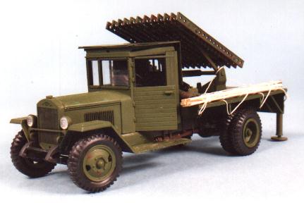
Zil Rocket Launcher By Ian Sadler
The kit used in this conversion is the Alan Hobbies Refueler chassis left over from the previous article and the Rocket rails from the Aero Plast BM-8-24 kit. The hull from this tank kit will be used for a further conversion. I started as usual by building the chassis and running gear, making sure I got it all level, square and set solid before the next part. The research then started as I wanted to produce the trials version of the Zil lorry with the 8-24 rocket launcher. I wanted to combine the two kits to produce the pre with the standard cab and not the modified ones used in the production series with a slope at the rear to allow for a greater depression of the rails to lower the silhouette for the transportation stage I used a combination of original photographs and scale drawings from various Russian , Polish, and East German books and magazines to determine the layout and the problems that lay ahead, far to many to list The majority of these I obtained in exchanges over the years from behind the Iron Curtain as it was then. Mostly in the early 1970 to 85 period. Also a set of original scale plans which at the time were to be published in a Polish magazine but to the best of my knowledge they never were. The cab was the first to tackle, I used the bonnet and wings and only the front windscreen section and the rear wall. The doors were made up from Slaters Plastic square section and cut to the measurements of the kit doors. I re planked the doors in a horizontal method as per a reference photograph, using plastic card scribed to represent the planking.The hinges came from Slater micro rod 30th in dia. The door handles were from the kit. The top of the cab was cut from several thickness of plastic card sandwiched together and shaped . By measuring up the top of the cab I was able to make the 3 blast plates from plastic card. I then noticed one little item; the blast plates not only hinge up and away from the windscreen but the plate on the roof of the cab is spaced out to keep it level. This was done with an incert of plastic strip along the front edge. Hinges were added to the rear edges of the plates from Slaters plastic rod 20th dia. After the cab had dried out and I was satisfied it had set square it was test fitted to the chassis. This was to allow me to measure up the flat bed for the base of the rocket launcher. The base was cut from two thicknesses of plastic card and sandwiched together to give the correct depth, the top one was scribed to represent planks. I glued it directly on top of the chassis and set it aside to set . All the chassis tie bars and plates were removed and new ones made from 40th Slaters rod with bolts made from a Grief accessory plate. The rocket launcher was built as per instructions but I modified the raising mechanism by adding small details seen in war time photographs and from the plans. After it was dry it was time to bring all the parts together for a test fit. As part of my research suggested that the early rocket launchers were placed on the centre line of the rear wheels. After the first test firings this caused instability. This was my first clue to the final placement. The second was that they had to bolt a steel blast plate at the rear of the rocket rails to prevent scorching to the wood or a fire on the cargo bed. The third and final clue was the stabilisers were bolted inboard of the rear deck and this also led to instability when firing the rockets. It now was a case of trying to make all these clues fit the model. Firstly I moved the rocket launcher base forward of the rear wheels centre line. This then showed an area that would need a blast plate. I marked this off on the bed plate with a pencil. The stabilisers I made from various diameters of plastic tubing and dry fitted them at the rear. I measured up the width of the bed plate and cut a piece of plastic to represent the plate to bolt the stabilisers to. I close up photograph showed an early stabiliser with a ratchet handle on the top to screw the bed plate down to the ground. This photograph also determined the depth of the fixing plate. This was my final clue and I was now able to assemble all the parts and complete a test fit. Not satisfied with the first the test fit, I then moved the rocket launcher further forward towards the cab. At last it all came together. I was confident enough to measure up and cut the rear blast plate out of plastic card then after a final check add glue to the parts. After the blast plate had set I added bolt heads to show how it was fastened to the wooden cargo bed. For these I use the ceramic beads from my water filter canister. See Tip section on these wonderful items at the end of the article. I measured up the space between the rear of the cab and the front edge of the rocket launcher and built a spare wheel holder from U channel for the base and sides and plastic rod to act as tie bars. This had to be built as a separate item from the main model and fitted after the final test fitting. It fitted like a glove. The last item to modified was the exhaust, it was fitted more closely to the photographs than the kit method.
I painted the model in my usual way as described in the previous articles, but used the black primer all over and then days later after masking the chassis. I sprayed a Russian Green very lightly on, this base coat gave me the shadows in the louvers to the engine panels and radiator . The rest of the model had two more light coats. After it has dried I picked out several areas for attention showing the rust effects this was done with a fine brush series 00000 using acrylics. wheels rims , exhaust etc. The wooden strips are made from long matches used for barbeques. I cut them in half lengthways and then thin down by scraping a blade along the length to give me planks. A very light wash of dirty colour adds to the weathering of them. Note the planks were used to go under the stabilisers to spread the load on muddy ground. Or under the front wheels for the same reason.
In the UK we have a Free Standing Water Filter jug. It has a canister filter in the lower part I remove the old filter canister and cut it open, empty the contents into a porcelain dish and dry them on the lowest heat in the oven . Do not attempt to dry them in a micro wave oven as they will explode and pebble dash your kitchen you have been warned . When they have dried out they change colour to a slightly off white. Disregard the black bits as they are activated charcoal unless you are into trains then they are great for the Steam Loco Tender. Using the beads could not be simpler. Drill a small depression in the plastic and add normal glue, wet the point of a cocktail stick and pick up the bead and place into the depression leave it to set. One canister will give you about 1,000,000 rivets or bolt head in 20 scales for about £2-75 UK prices . The best buy in the UK is Boots the Chemist's own make for hard water. Text, Models and Images Copyright © 2000 by Ian
Sadler
|