Home
| What's New |
Features |
Gallery |
Reviews |
Reference |
Forum |
Search
Home
| What's New |
Features |
Gallery |
Reviews |
Reference |
Forum |
Search
|
|
|
Vertol (Piasecki) H-21/V-43A by Jan Teipel
The original Piasecki PD-22, labeled H-21 by the US Army and Air Force, had its maiden flight in April 1952. The helicopter set some official records in 1953 with a speed of 127,52 mph (236,15 km/h) and a maximum altitude of 22,288 ft (6,795 m). The aircraft carried up to 14 passengers or 12 stretchers. Later models lifted up to 20 fully equipped soldiers. Approximately 400 aircraft served worldwide (Canada, France, Germany, Japan, Sweden, USA). At the height of its use, the US alone had 10 squadrons of H-21 active. Near the end of the 1950s, the US Forces tested the H-21 as a Gunship with heavy weaponry mounted on the front landing gear.
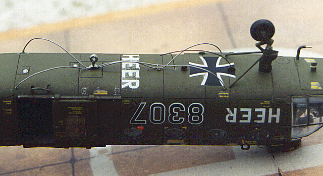
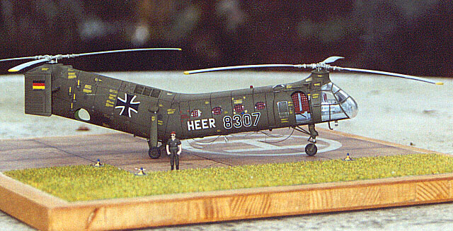
The Bundeswehr acquired a total of 32 H-21s (Vertol V-43B), the first in 1957. Five served with the Luftwaffe, the rest with the Heeresfliegertruppe. A contest against Sikorsky's H-34 showed the Choctaw's higher potential, so the H-21 was not obtained in higher numbers. In 1968 the HFlgBtl 300 (the unit flying the H-21) reported 30,000 flying hours. Final flight for the German H-21s was on the 8th of December 1972 , several "bananas" survive in German museums.
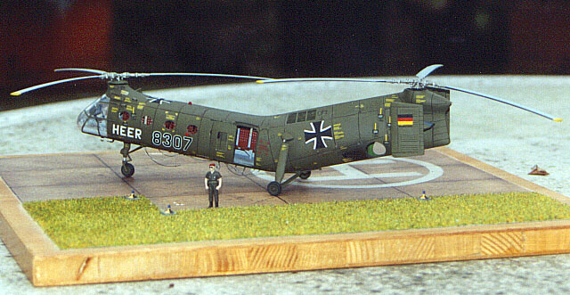
Revell's kit of the H-21 Shawnee was released in 1999. The kit was originally released by Italeri. Even so, it is a vast improvement over Hobbycraft's older kit. Over the past few years, I have been built several Heeresflieger whirlybirds kits in 1/72 scale as gifts for my uncle. He served as a technical officer in the German Heeresfliegertruppe (army aviation) and the H-21 was the first helicopter with which he had a close acquaintance. This is the fourth of six models I am going to build for him. I recently finished the model as a Christmas present (alas late, due to a modeling-accident). I hope you like what I achieved because I am not a very seasoned modeler, this being the eighth kit I have seriously built. I'd like to tell you how I did it, so you can avoid some pitfalls and errors and even enhance the model somewhat. I will to follow Revell's instructions loosely with my explanations. The text includes some further improvements that I did not include, mainly because I had a tight schedule to meet, but also because some of the necessary information came up after I had the model finished.
Cabin and Cockpit
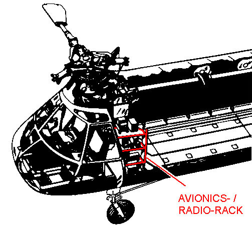
Some styrene blocks (painted black) pose as radios, thin wire could be added. The instrument panel should be painted FS 36231 (typical) with black instruments, plus the usual drybrushing with white, a few red details and gloss coated "glasses". I do not recommend cementing any cockpit parts to the floor at this point because this can easily be done later and the parts are endangered in the open fuselage front (Believe me, this slows you down!). Fix two 1.5mm (0.06in.) wide, thin strips of sheet in front of each seat, running just clear of the pedals about 1.5mm (0.06in.) over the front of the main floor.
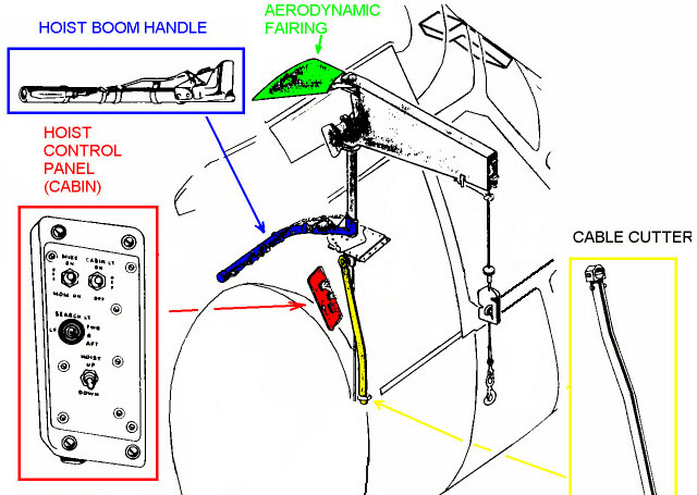
Paint the whole floor light grey (see above) and the top of the center-console black. Add two pieces of stretched sprue for engine control levers to the right middle of the center-console. You could further improve the cockpit with Eduard's PE set, but it looks quite busy without and the rest of their set goes into places almost invisible later. Add a cable channel to the cockpit bulkhead, using a 1.5mm (0.06in.) wide, thin strip of styrene running almost from the top vertically down to the floor to the right of the pilot's seat. Paint the cabin's aft bulkhead light grey, touch up the curtain with a different shade of grey and cement the bulkhead perpendicular to the floor. Then glue the front bulkhead in and test the fit with the fuselage side! (Tilt it forward to much and the interior will not really fit in.) Add the hoist enclosure, and if you're really into superdetailing, add a hoist boom handle (black) and a cable cutter (yellow), made from thin wire, to the fuselage inside between hoist enclosure and door.
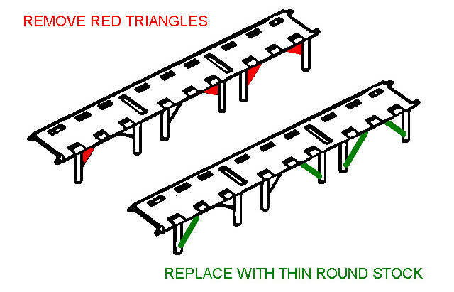
Paint the cockpit seat cushions brick red and add 1mm (1/25in.) wide strips of masking tape for shoulder and lap belts (grey) with a thin slice of round sprue as a lock (aluminum). Remove the plastic triangles from the cabin benches, then add round styrene instead.
Paint the benches as instructed, add grey lap belts with rectangular locks, using the same technique as for the cockpit seats. If you add belts to the seat next to the door and to the four seats opposite of the door, that's all one can see later. Add the benches to the cabin, weather the floor with aluminum drybrushing (or an artists silver pencil) and grey/brown pastel chalk powder.
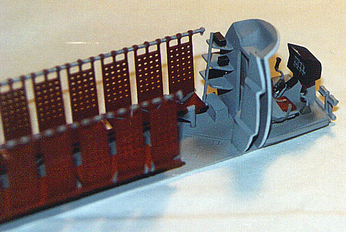
Engine Area When building the drive shaft compartment, keep in mind that there can be no full "floor", because this is also the air intake for the engine. Since I have no photos of that area, I just painted part of the "floor" black. The back of the engine looks quite convincing OOB, just paint the rhomboid recess black and the engine itself in several metal tones. Italeri/Revell furnishes the kit with Nylon (?) mesh for the intake, cut it to size with a sharp blade, pressing straight down, do not drag the blade. If you measure the recess inside the fuselage sides and cut cautiously parallel to the strands you will have (but shouldn't need) enough mesh for errors. Thin the insides of the intake spars, so that the mesh can sit closer to the outside of the fuselage. Glue in the mesh with CA glue, carefully pressing it into the fuselage curve.
Fuselage Paint the area below the aft rotor also chromate green or yellow - it remains visible! Paint the cabin walls FS 36231. Draw two thin lines with a pencil, spaced 1mm (1/25in.) apart, along the cabin windows' tops and bottoms, simulating fuselage stiffeners. "Hide" the area inside the front rotor dome by painting it flat black. After the paint has dried, mask the complete inside of the engine area and air intake and then paint the outside vicinity (incl. mesh) olive drab. I lined the inside of the mesh with tissue, to absorb paint overflow and to avoid getting masking tape stuck to the delicate mesh. You could add the transmission tunnel to the cabin roof by adding two pieces of plastic with a trapezoid cross section and a rounded top (H: 2,5mm / 1/10in.; W: top 6mm / 0.24in., bottom 5mm / 0.2in. ). Using two pieces ensures easily that you will get no gaps that are visible from the doors. (see sketch 6) Glue all the cabin windows in and mask their outsides for protection.
When joining the fuselage halves, be advised that the panel lines do not match precisely. Thus, before joining the subassemblies, sand the mating surfaces flat (removing the locating pins thereby). Dry fit all interior parts (The aft bulkhead is to small!), when you have decided on their optimal placement, fix them to one fuselage half and then glue the halves. Align the halves so that the panellines on top match as well as possible, it is easier to sand a little around the front rotor dome and at the end of the fuselage than to rescribe the mismatched lines. By the way, since some corrections are needed on the underside, you don't have to care to much for the alignment of the lines there. Insure that the cockpit floor sits tightly to the fuselage bottom, there might be a gap in front. Build the T-shaped stabilators, but keep them off the fuselage for ease of painting and decalling. Pay attention, when mounted, they should NOT sit obliquely to the ground, this is the result of getting the parts mixed up. Check which stabilators to use, early H-21s had the trapezoid, later models the parallelogram style. Also do not glue the exhausts in, this is best done after painting and finishing.
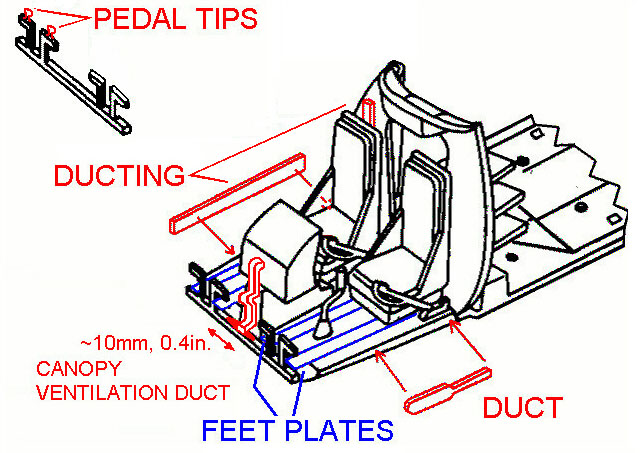
Detailing the Cockpit Paint the collective sticks light grey with a flat black grip and an aluminum ring below the grip. Paint the cyclic pitch controls light grey with a light olive brown cloth cover on the base of the stick and a black grip with red switches. Enhance the pilot's pedals with foot-sized hour-glass shaped pedal tips on top, made from thin sheet. Glue in the pilot's collective, the seats, the copilot's collective, the cyclics, the instrument panel and the pedals. There is a light grey ventilation duct running from the instrument panel's back down to just above the pedal bar, then toward the canopy, where it bends outward into two tapered black outlets, these reach in front of the inner pedal. The duct seems to be made of some crinkled insulation, which could be represented by folded, crinkled aluminum foil, its outlets by tapered round stock. Dry fit thoroughly with the canopy! Along the vertical sides of the cockpit floor there are cable ducts. On the pilot's side, use a thin, 1.5mm / 0.06in. wide piece of styrene sheet running from the cockpit's back to it's forward corner. On the copilot's side the duct is paddle-shaped.
Finishing the Canopy
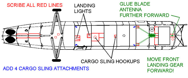
Fuselage Exterior Enhancements On the bottom you might want to scribe some panellines and add two landing lights: Mill out their reflectors, paint them silver and simulate their glass with drops of 5-minute epoxy.
Further on, it's easy to enhance the navigation lights on both sides of the fuselage, sand them almost completely down and paint the flat, drop shaped areas silver, then mask them (more later).
Mask the cabin doors' openings from the inside with tape, paint the inside light grey, when dry, attach them over their respective fuselage openings with liquid masking film. Glue the kit-supplied anti-collision-lights on and only mask their outer halves. Mask all mounting holes for small parts with liquid masking film, taking care not to blob around the holes. Mask the rotor dome openings with rolled tissue. Paint the entire fuselage olive drab, maybe touch up some panels with a lighter shade. Pay attention not to spray paint into the engine air intake and outlet! After painting the fuselage, remove the doors and touch up around the door openings. It is important to achieve a glossy finish because the decals tend to develop a slight silvering and also have to conform to some pretty irregular surfaces. When decalling, check the relative position of the bigger decals on the fuselage, do not trust the plan, since it shows some stencils to small. I had to remove the left side aircraft number, which was quite an ugly job! Use deliberate amounts of decal softener (I had Micro Set&Sol), otherwise the stencils won't conform well. Seal the fuselage and stabilators with clear flat.
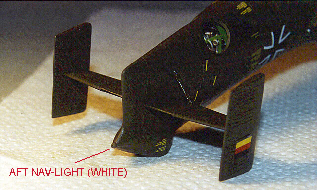
Glue the windows to the doors, some aircraft had a window frame running horizontally over the middle. You could remove the upper door rails and replace them with wire. Mount the stabilator-assembly. Paint all small parts on their sprues, cutting some of their attachment points first (less touch up-work later!). There are silver oleos on the landing gear struts (front: between the scissors, aft: below the drop-shaped fairing). Fill the ejector-mark in the baseplate of the aft landing gear with CA glue and add two small U-shaped hatches. Carefully glue the baseplate into its opening. The rescue hoist boom on the right side has a trapezoid fairing between fuselage and upper hinge, shape this from 1mm (1/25in.) sheet and give it an "aerodynamic" sanding. I exchanged the pitot tube for an L-shaped assembly made from a very thin dentist's syringe and a wider normal one. I flattened the vertical part of the pitot tube to an oval shape. Make the drop-shaped side position lights with 5-min epoxy glue, the layer of silver paint really lets them sparkle! Add a clear position light to the tip of the end of the fuselage, use clear sprue sanded to shape or take it from your spare parts box.
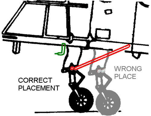
Mask all lights with liquid masking film. Reposition the nose landing gear forward, so that the strut's back end is just forward of the panelline. This also goes for the unfaired landing gear that other countries' H-21s had. I replaced the V-shaped strut of the nose landing gear with sturdy, thin wire for stability, adding a short piece of wire to the gap to simulate the hinge.
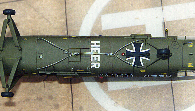
I also replaced the tubular step below the back door with a bent-to-shape wire which I glued into deepened holes with CA. Do not hang part 40, the cargo-sling hook, to the step (as the instructions tell you to do). Flatten the tyres a little bit, but keep in mind the perennial discussion about overdone bulging of tyres! Paint a tiny red control stripe over the tyre/rim border. Now weather the aircraft with fine tipped artists pencils (for the panellines) and pastel chalk dust for all other stains. I simulated worn paint, especially around the engine area and on the door sills with a silver pencil. Seal the weathering with another coat of clear flat. Glue the exhausts (painted burnt metal before) into their recesses. Paint the position and anti-collision lights with clear acrylic colour: red for top, bottom and left side, blue for the right side. Add a whip antenna (3cm / 1.2in.) and its base to the fuselage bottom. Add the cargo-sling, using two strands of thicker fishing line, sewing thread or thin wire (9cm / 3.5in.). Sand a grove along the top of the Y-shaped hook (Pt. 40) and glue it to the strands approximately 3cm (1.2in.) from their aft end. Connect the strands with a tight wire loop (as a shackle) a further 2.5cm (1in.) towards the front. Glue the ends of the "cables", the shackle and the hook to the fuselage as shown in the photo.
Paint the cargo sling with steel colour. If you want to add the homing gear to the nose, replace the antennas with stiff, straight black hair.
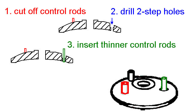
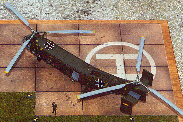
Rotors The blades should hang downward from the rotor head (even the hinge part of each blade is bent down on most photos). Paint both sides of the blade tips with a dull yellow stripe up to the thin engraved line. Replace the control rods with thinner round stock. For the front rotor, drill stepped holes trough the round cover plate and glue in the replacements.
I did not secure the rotors in their mounting plates, they sit securely without and stay detachable, e. g. for transport. Viewed from above the front rotor turns counter-clockwise, the aft rotor clockwise and the cover plate belongs to the front rotor, according to all photos. I don't know, but maybe Italeri has an error in their instructions here, since I have seen two nicely built H-21-models with the cover plate mounted aft.
Building the new Shawnee kit was a enjoyable project despite the kit having some errors, but they are easily corrected without major model-surgery (At least if you know about them soon enough!). If you like helicopters, this kit is definitely worth building. Further more, the kit offers opportunities for super-detailing that can be used even by less experienced modelers. I hope my step-by-step description comes in helpful for those interested. Naturally, while writing this feature, I have found some errors in my work, the most important being the nose gear mounted to far back. Well, I am still satisfied with my Shawnee, especially since this was a first for me in two ways: The first kit that I finished quickly on a deadline and my first kit built with the (successful) desire to present it to the public.
Preserved H-21 at the Hubschraubermuseum in Bückeburg, 40km (25nm) west of Hannover. http://www.hubschraubermuseum.de F-40 Flugzeuge der Bundeswehr, No. 11, Arbeitsgemeinschaft LUFTWAFFE e. V. (Lots of photos, five-side-views, some historical and technical notes) Review in Fine Scale Modeler, February 2000 Walk-Around photos at http://www.aircraftresourcecenter.com www.rotors.org a homepage of a Californian helicopter-museum Text, Models and Images Copyright © 2000 by Jan
Teipel
|

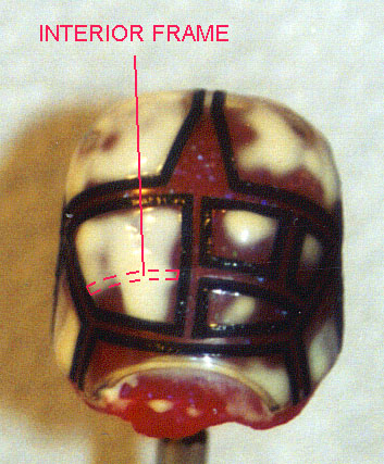 German
H-21s had a distinctive feature, the horizontal canopy frame in front of
the copilot's eyes was just on the inside, visibly light grey from the
outside and there was no vertical frame to the copilot's left front. The
kit part has thin raised lines on the inside for the horizontal grey
frame, polish the inside (I used polishing cream for plastic
watch-glasses), mask, paint, then coat the dried inside with Future floor
wax (see Hyperscale's Forum for it's name in other countries). I found
masking with parafilm to complicated because the framing is very delicate,
and used narrow electronics masking tape (made e. g. by Mecanorma, used
for designing PE circuitry) for the borders and liquid masking film for
the areas.
German
H-21s had a distinctive feature, the horizontal canopy frame in front of
the copilot's eyes was just on the inside, visibly light grey from the
outside and there was no vertical frame to the copilot's left front. The
kit part has thin raised lines on the inside for the horizontal grey
frame, polish the inside (I used polishing cream for plastic
watch-glasses), mask, paint, then coat the dried inside with Future floor
wax (see Hyperscale's Forum for it's name in other countries). I found
masking with parafilm to complicated because the framing is very delicate,
and used narrow electronics masking tape (made e. g. by Mecanorma, used
for designing PE circuitry) for the borders and liquid masking film for
the areas.