|
Curtiss P-40N
by
Fred Hocker
|
 |
|
Curtiss P-40N |

HyperScale is proudly supported by
Squadron
The last and most numerous production variant of a venerable airframe
that began as the radial-engined P-36, the P-40N featured a lengthened
fuselage/tail to correct swing on takeoff, a lighter structure, uprated
engine with revised shuttering over the cooling air intakes, a revised
canopy and fuselage spine, and increased armour protection. Over 5,000
were produced, and the variant saw service on several fronts with the
USAAF, the RAF (as the Kittyhawk IV), RAAF, RCAF, RNZAF, and others,
often in the ground attack/support role. Not bad for a design considered
already dated when the US entered WWII.
|
Eduard's 1/48 Scale P-40N "Profi-Pack" |
This kit, unusually for Eduard, is essentially a reboxing of someone
else's product. The basic injection-moulded components are Mauve's
well-reviewed P-40N, supplemented with resin cockpit and wheels by
Aires, etched nickel-plated brass by Eduard, and decals by Aeromaster.
With this combination of manufacturers involved, it is hard to see how
this kit could go wrong.
|
Kit
Details |
-
Manufacturer:
Eduard
-
Subject: Curtiss
P40N
-
Scale: 1:48
-
Cost: 238 kr.
-
Format:
Multimedia
|
The Mauve contribution comes on four sprues of very dark green
(almost black), soft plastic. The quality of moulding is very high, with
small sprue gates, crisp detail, good mould alignment, and sound, simple
engineering. Locating pins and recesses abound, so there is no question
where any of the parts go. This plastic is consistently reviewed as the
best P-40 in 1:48, with the only negative remarks concerning the cost
and the need for additional detail in the cockpit and wheel wells.
Accuracy is pretty high, with only a few quibbles. I note that the
contours of the undercarriage fairings are slightly off and that a few
notable openings at various places are missing, such as the intakes in
the wing roots and the gun camera port in the starboard gear fairing.
Hardly worth mentioning.
The Aires resin and Eduard brass address the lack of detail quite
effectively. Nine resin pieces include two wheels (bulged and flattened,
with block tread of apparently appropriate pattern), a finely detailed
cockpit floor, two sidewalls with lots of relief, a back wall, a very
thin seat, a revised set of radiators, and a bomb. These are up to
Aires's usual standards and the mould blocks are easily removed on each.
The etched fret includes belts, detailed inner and outer surfaces for
the radiator flaps, numerous levers and knobs for the cockpit, shutters
for the radiator intakes, fins for the bomb, etc. There are three
different instrument panels with the appropriate sheets of film
instruments, to accommodate three different sub-variants in the “N”
series.
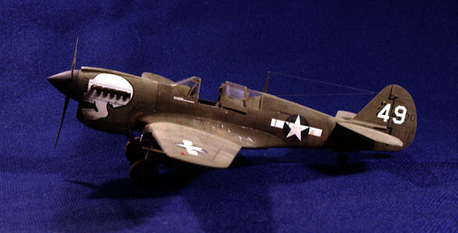
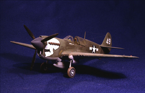
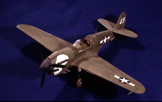
The Aeromaster decals provide markings for four aircraft: "49/Joanne" of
the 89th FS/80th FG, USAAF at Karachi, India in 1943 (nose art features
a large white skull on the cowl); 74th Squadron, USAAF, at Kweilin,
China in 1944 (with the traditional shark's mouth on the lower cowl);
"Gloria" of the 18th Squadron, RNZAF, in the Solomon Islands 1944; and "PN"
of the 132nd Squadron, RCAF, on home defense at Boundary Bay, British
Columbia in 1944-45. The decals are clear, opaque, and in register, with
a million tiny stencils. Comparison to photographs of the subject
aircraft suggests that some of the markings are incorrectly sized.
Instructions are in Eduard's standard five-colour, pictorial format with
clear indications of where everything goes and four views for each
marking option. Painting information is reasonably detailed, and keyed
to Tamiya, Humbrol, Testors, Revell and Aeromaster paints.
Because the Mauve kit has been extensively reviewed elsewhere, it
needs little comment from me except to say how well it goes together. A
small amount of cleanup is needed here and there (the landing gear
fairings at the leading edge of the wing are a bit fiddly) but nothing
serious. The fuselage needs to be spread rather a lot to meet the edges
of the upper wings, but this is engineered in, with the cockpit floor
acting as the spreader. My fuselage had a slight warp in it, which
tended to give the fin a little too much left trim, but this was easily
removed by careful clamping while cementing the fuselage halves
together.
The Aires cockpit (which is available separately) competes directly with
a True Details cockpit that most reviews of the original Mauve kit
recommended, so a little comparison here might be in order. Both sets
take the same basic assembly approach aft of the instrument panel -
separate floor, sidewalls, back, and seat - but build the front
differently. True Details uses a large front block, which effectively
blanks off the space forward of the cockpit, has the rudder pedals
moulded in, and provides a mounting point for a detailed resin
instrument panel. Eduard/Aires do without a front piece of any kind (so
a blanking plate is needed), and use etched pedals and panel, with the
pedals mounted to the floor and the panel directly to the fuselage
halves. Eduard keep the injected gunsight, control column and that other
stick on the floor (what is that? auxiliary hydraulic pump?). The two
sets disagree on the type of seat and some of the sidewall detail.
Generally speaking, the Aires set has more fine detail (every rivet and
panel line in the cockpit floor, all the stamped reinforcement and
rivets in the seat, for example), but leaves out some rather obvious
bits (no throttle linkage). The Aires/Eduard cockpit also uses lots of
little etched bits for levers, handles, and linkages. The Aires cockpit
does not include a gunsight, you have to use the injected part, which is
not only very crude but not very accurate (it does not project above the
"dashboard"). If you prefer all of your detail moulded onto solid blocks
and don't like the "flat look" of etched details, True Details is for
you. If you like etched panels with film instruments and abundant
microscopic surface detail, Aires should be your choice.
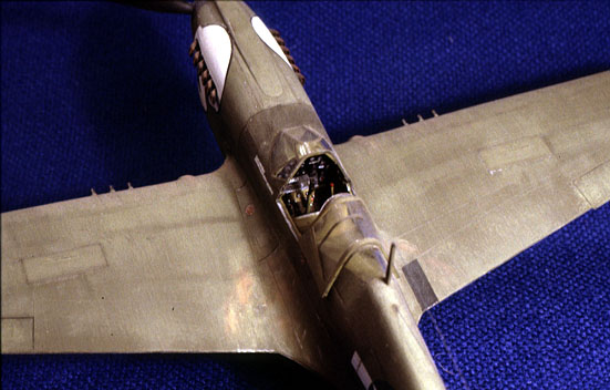
I like the mixed resin and etch approach, if the materials are used
wisely, and this cockpit is reasonably well engineered. The bits all fit
with little work and the breakdown makes painting easy. There are only
two real flaws. First, the cockpit floor, as the kit is engineered, also
forms the inner sides of the wheel wells, but this was not taken into
account when making the resin replacement for the kit part. It is too
shallow and devoid of detail, and so will need its sides extended to
finish boxing in the wells. I did this by sanding off a little bit of
the sides and gluing on pieces of styrene sheet. This also gave me the
chance to adjust the fuselage-to-wing fit a little, since the floor acts
as a spreader. Second, there is no front to the cockpit and you can
actually see into the dark void, with or without a penlight. I solved
this with a simple sheet of styrene painted in a darkened shade of the
cockpit interior green. While I was at it, I also made the throttle
linkage out of three pieces of 0.3mm wire and a small rectangle of
styrene, drilled to act as the guide piece. I replaced the seat mounting
rails, which are supposed to be tubes but are supplied as flat etched
pieces. I used the injected rudder pedals, as they look much more like
the real thing than the etched ones. These have to be separated and
little holes drilled for them in the floor, as the injected parts have
the pedals too close together.
The instrument panel lacks the extension below the lower part that
appears in most of the cockpit photos I can find. This panel has the
heater controls, etc, and sat between the pilot's knees. It would go a
long way toward hiding the gaping hole ahead of the panel. I
scratch-built this from sheet styrene and bits of rod for knobs.
The instructions indicate that the cockpit floor should be glued to one
side of the fuselage early in the construction process, but test fitting
revealed that it can be inserted after the fuselage is assembled. I
chose this route, as it was much easier to get the fuselage halves
aligned and cemented without the stress added by the spreading action of
the cockpit floor. This approach also made it easier to get a good fit
at the wing root, by adjusting the width of the cockpit. The
wing-fuselage fit is nicely engineered, and if you get the cockpit floor
sized properly, it drops right in. I had very little filling to do
except at the complex join at the leading edge, where the undercarriage
fairing is also involved.
The replacement radiator intake plate in resin is rather difficult to
fit into the nose, as there is little in the way of positive locating
points for it and the contour as moulded does not really match the
fuselage interior. It is also difficult to get it to stay put in one
half while test fitting. Once it was close, I decided to live with it. A
little filling was necessary just under the spinner. Of course, after it
was in place, one of the clever two-piece etched shutter assemblies fell
off, and it is nigh on impossible to get it back into place through the
small opening!
Despite the resin and etched additions, this kit could still benefit
from some detailing in a few places. The improvements I chose to make
were:
-
The machine gun fairings do not line up
very well when the wing is assembled, so I replaced them with styrene
rod drilled to take gun barrels, which were drilled out (slightly over
scale, as a .50 cal bore at 1:48 is smaller than a no. 80 drill bit, the
smallest I have).
-
I drilled out the vent holes in the
perforated plate forward of the exhaust, the intakes in the wing roots
and the gun camera port in the right undercarriage fairing.
-
I made new main undercarriage doors, as the
kit items were too plain. I built up the doors in the same manner as the
real thing, inner and outer skins on small bulkheads, with a small lug
for the retraction linkage. Can’t see’em, but I know they are there.
-
The lower ends of the main oleo legs are
incorrect and the torque links are not at all like the real thing, so I
clipped off the bottom ends of the legs and made new ones of styrene
rod, and built new torque links.
-
The addition of brake lines, usually an
easy detail, is complicated in this case by the peculiar nature of the
P-40 undercarriage. Because the main leg rotates 90 degrees before
folding back, there has to be some play in the brake line. There are two
little rods on the leg, one at the top and one about halfway down, to
keep the line clear and to keep the extra length from flopping around. I
considered adding the rotation gears at the head of the main
undercarriage leg, but this seemed like overkill.
-
I replaced the tailwheel doors, which are
far too thick and do not open at the right angle, and added the door
retraction linkage.The radiator flaps are very nicely done by Eduard and
make up into a convincing assembly. The outer surfaces are a single
piece with the aligning slides connecting them, while the inner surfaces
are four separate pieces. I added actuating rods from fine wire. The
only problem is that there is nothing in the radiator housing, so the
open flaps reveal a void, which I failed to anticipate. If you want to
model the flaps closed, the plastic part fits just fine.
-
The sway braces for the bomb/drop tanks as
supplied are far too heavy. The originals look almost fragile. I
replaced the kit parts with fine rod and tiny discs.
-
The aircraft I chose to model is shown in a
period photo with the drop tank mounted backwards. This appears to be a
semi-permanent mount, based on the staining, and required an extended
filler neck. I chose to replicate this, as well as some extra detail on
the tank itself.
The basic paint scheme for late production P-40s should be very
simple, olive drab (with green splotches on horizontal surfaces as they
came form the Curtiss plant) over neutral gray, but the N series spans
the transition from the early-war shade of o.d. (41) to the darker
late-war shade (ANA 613). The scheme I chose from those supplied in the
kit, the 80th Fighter Group machine (no. 49) flying ground support in
the CBI theater, is an early production airframe (P-40N-5) dated to 1943
and should be the earlier shade (I used Aeromaster acrylic). Photographs
of this aircraft suggest heavy weathering with the upper surfaces
sun-faded, and partial respray of the fuselage from the windscreen back
to the tail. I chose to try to replicate this appearance. Various shades
of lighter and darker olive were used to create the contrasting tones,
applied as washes or drybrushed as appropriate (darker tones,
representing unfaded paint or respray, should go down into the cracks,
while lighter tones, represented faded, scuffed paint should not).
With the basic fading and patching of the principal finish complete, the
decals were applied over a coat of "Selvblankende Gulvpolish," the
Danish equivalent of Future. I began with the major markings, and it was
readily apparent that someone at Aeromaster is not doing their homework.
The national insignia were too small by at least 20%, and the locations
given in the instructions do not match up with photographs of the
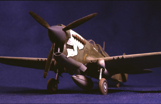
original aircraft. The large skulls are in fact too large by just enough
that the upper edges run up onto the intake scoop on top of the cowl,
which is too far. In addition, this large decal will not conform to the
changing contours of the nose without cutting several slits around the
edge and infilling some gaps thus created. Very frustrating. Even with
softener, the decals did not sink down into the surface detail, so all
the panel lines that go under them have to be rescribed. They were also
prone to silvering, even over Future and with plenty of setting
solution. A light scalpel cut and a little Future desilvers them quite
nicely (Future really is the wonder drug of modelling).
Looking at the photograph from which I am working, it appears that all
of the stenciling was not reapplied in the resprayed areas. Thus I have
left off many of the stencils in this area, and toned down (faded) those
in the areas still in original paint. The manufacturer's logos on the
prop blades seem to disappear almost instantly in the field, although
the stenciling near the hub seems to last longer. so I omitted the logos
but kept the stencils.
With the decals on and "de-silvered," a coat of flat varnish (Humbrol)
was applied to even things out. This was followed by an oil paint wash
(various combinations of black and burnt umber) to simulate oil leaks
and stains as well as accumulated dirt in the crevices and some
drybrushing of brown tones on the lower fuselage, drop tank and landing
gear to mimic the dirt thrown onto these areas by prop wash.
Finally, the last little bits could be added, such as the gear doors,
pitot probe, antennae, and the drop tank. The last act was to add a gun
sight from Cutting Edge.
It is hard to convey how much I enjoyed this project. I have always
liked the look of the later P-40, with the deep chin radiator and long
tail, and the kit was a good start toward an entertaining exercise in
detailing and weathering. I don't know that I would build another, as I
rarely do multiples of the same kit, but I would cheerfully recommend it
to others.
Click the thumbnails below to view larger
images:
Text, Images and Model Copyright © 2001 by
Fred Hocker
Page Created 05 December, 2001
Last Updated
04 June, 2007
Back to HyperScale Main Page
Back to Features Index |
 Home
| What's New |
Features |
Gallery |
Reviews |
Reference |
Forum |
Search
Home
| What's New |
Features |
Gallery |
Reviews |
Reference |
Forum |
Search