Squadron.com
It has not been easy to model an A-4M Skyhawk without "moving
mountains" in scratch building and detail work. I did it once using Monogram
A-4E/F and OA-4M kits. I was happy with the result, and I always wanted to do
another. But, being unwilling to tackle the conversion a second time with
Monogram kits, I just let it go.
Times have changed. Along came Hasegawa with a simply gorgeous A-4E/F kit. All
the desire to build another A-4M came out in force. All I needed was some time
to start grafting Monogram OA-4M pieces onto it -- NOT! I knew that surely
someone would release a conversion to make my life easier. Either that or
Hasegawa would release an A-4M kit of its own. Just before IPMS Nationals in
July of 2002, the former of these possibilities happened with Cutting Edge
releasing an A-4M conversion for the Hasegawa A-4E/F kit. Of course, this was
not a huge surprise, since I did help with some of the research. For a review of
the Cutting Edge A-4M conversion, click here.
Then, I needed decals to put on this A-4M model. All the major manufactures have
released Skyhawk decals to go with the Hasegawa (and HobbyCraft) Skyhawk kits.
But Cutting Edge was first with a series of sheets dedicated to the A-4M (in
support of their conversion set). For a review of the Cutting Edge A-4M decals,
click here.
I originally started this model before the IPMS Nationals with the intent to
finish in time to take it to Nationals so Cutting Edge would have a finished
model to point at with all their new A-4M releases. With model building being a
motivational exercise (for me), I needed to maintain motivation to finish this
project. Sadly, after pushing hard on a number of time-critical projects
completions early in the year, my motivation levels in July were starting to
drop. When I hit a minor snag, the model missed getting done for National. In
fact, it only finally got done this month. I have to apologize to Cutting Edge
for not getting the model done in time.
I am not going to get into the basic Hasegawa kit here. I have
written several reviews of the various versions already released by Hasegawa.
You can go to these reviews to read all the great things about these kits. The
point of this writing is to discuss the Cutting Edge A-4M conversion to the
Hasegawa A-4E/F kit.
Cutting Edge A-4M Conversion
To build an accurate middle or late production A-4M requires
some changes to the cockpit, especially the main instrument panel and instrument
hood. Not wanting to do this on this model (and knowing the Cutting Edge was
already planning to release a late production A-4M cockpit set), I chose to
build an early production A-4M. The first A-4Ms (early production) were quite
similar to the A-4F in their avionics fit and thus their cockpit
instrumentation.
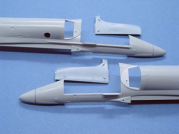
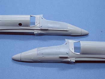
The conversion of the A-4E/F kit into an early production A-4M really only
requires one fuselage cut. The cut is made on both fuselage halves in the area
of the cockpit. Cutting Edge provides insert pieces that replace these areas of
the fuselage so as to correct the shape of the cockpit canopy and windscreen.
This change, by itself, is the only heavy surgery needed to turn an A-4F into an
early A-4M. The pictures below show the cuts to the fuselage halves and the
fitting of the insert pieces.
|
|
|
| Cockpit
Fuselage Cuts
|
Fitted
Cockpit Side Walls
|
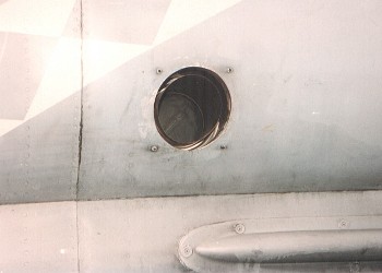
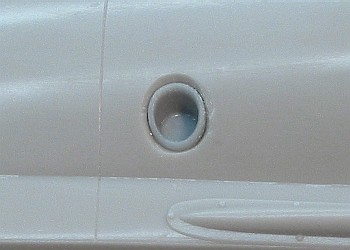
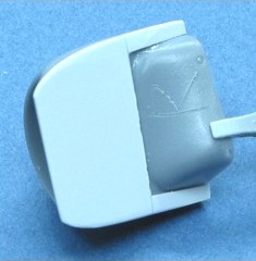
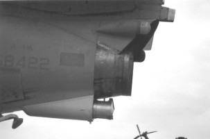
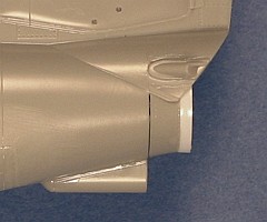
The only other surgery required is the installation of the APU
exhaust port on the right fuselage. Cutting Edge provides the exhaust port. All
that is needed is to create an appropriately sized hole in the correct location
on the right fuselage. Sounds easy, huh? Well, it was. I eyeballed the location
of the APU exhaust from reference pictures and drilled a pilot hole with a small
diameter drill bit (0.037"). I then enlarged this pilot hole with a 1/8" drill
bit (which matches the size of the Cutting Edge APU exhaust piece.
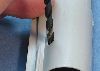
Note that the APU exhaust comes out parallel to the ground, not perpendicular to
the lower engine intake contour. After drilling the hole in the fuselage, I
twirled the drill bit in the hole as I pulled up on the angle of the drill bit.
This re-contoured the hole to place the exhaust port at the correct angle.
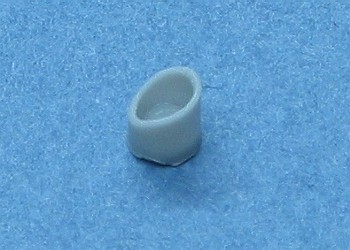
Cutting Edge created the exhaust port with a uniformly squared off pipe. The
Cutting Edge instructions say to glue in the APU exhaust, then trim off the
excess. I prefer getting the shape right before gluing, so I filed down one side
to change the lip of the pipe to match the contour of the fuselage side. Then, I
glued it in place. See the following pictures to better show what I am trying to
describe.
|
|
|
|
APU Exhaust Port Location
|
Filed
Down Exhaust Pipe
|
|
|
|
|
Drilling Angle for the APU Exhaust Port |
Completed APU Exhaust Installation |
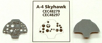
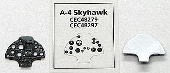
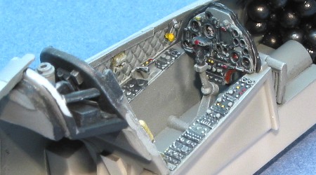
With what I thought was the last of the surgery behind me, I
continued to build the kit. I chose to use the Cutting Edge A-4 Skyhawk cockpit
set (CEC48279). This is an A-4F cockpit, but it is correct for an early
production A-4M. I even decided to give the main instrument panel the sandwiched
acetate treatment as provided in the Cutting Edge set. See the pictures here for
the outcome of my work.
 |
 |
|
Unpainted Main Instrument
Panel |
Completed Main Instrument Panel
|
 |
 |
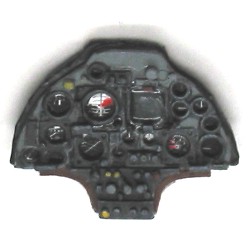
|
Painted Main Instrument Panel |
Completed Cockpit Tub |
The only trick to watch on the cockpit assembly is the alignment of the back
wall. If you look at the fuselage around the cockpit, you will see a diagonal
panel line running down from the rear quarter point of the cockpit sill. This
panel line corresponds to the location of the back wall of the cockpit. When
attaching the back wall into the cockpit tub, I needed to check and recheck the
alignment of the wall with this panel line. After three attempts at it, I
finally got it to align where I wanted it. Once aligned correctly, the rear deck
piece fits perfectly into the thinned out lip area of the fuselage at the rear
of the cockpit.
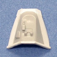
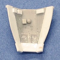
After assembling the fuselage, I went to install the instrument hood over the
main instrument panel and forward cockpit. Since Cutting Edge provides no piece
for this in the basic A-4M conversion, I turned to the kit piece. For an early
production A-4M, the kit piece details are correct (with only a gunsight, no HUD),
but the piece is quite a bit too small for the enlarged opening of the cockpit.
I added strip styrene around the kit piece to enlarge it so it could fill the
needed space. I used 0.020" styrene strips, 0.100" wide on either side of the
kit piece. Then added some small scraps to the forward area to finish the work.
It was crude, but it was enough to mount the piece onto the fuselage. Gobs of
super glue did the rest for fairing the enlarged instrument hood into the
fuselage, under the windscreen.
It was this issue (modifying the instrument hood) that ultimately deep-sixed
getting the project done for Nationals. In my opinion, it would not have been
hard for Cutting Edge to provide a replacement instrument hood in the basic set.
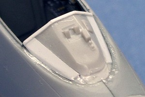
If you want to build an early A-4M (that does not use the late cockpit update
set), use my measurements above and pictures below to guide your work on growing
the kit instrument hood to fit the enlarged A-4M cockpit opening.
 |
 |
 |
|
Modified Hood -- Top
|
Modified Hood -- Bottom
|
Modified Hood -- Installed
|
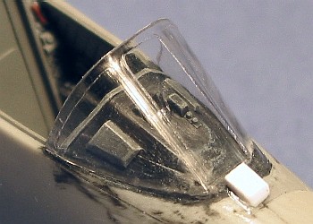
With the instrument hood attached, I painted the area and then attached the
windscreen. The fit was less than perfect, but nothing that I could not fix. The
upper nose is a rounded surface. The leading edge of the windscreen is straight.
After consulting some pictures of A-4M windscreens, I found the top of the A-4M
nose is a bit flattened to work with the revised windscreen, so I used a flat
file and flattened the top of the nose a bit to better match the windscreen. A
little super glue along the edges completed the filling of the seams.
One detail item missing in the conversion is the rain removal and de-icing vent
in front of the windscreen. I added this detail using a short piece of 0.030"
strip styrene. The image below (left) shows the attached windscreen with the
rain removal and de-icing vent.
 |
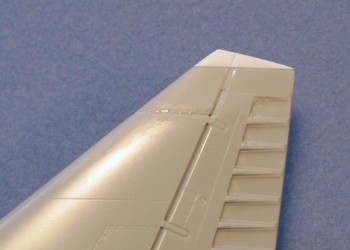 |
Another revision to the kit involved the top of the vertical
tail. As an early production A-4M, this model has the squared fin tip (kit part
A14). I have never liked the squared fin tip as molded by Hasegawa. The Hasegawa
part has a "level" contour that just does not look right to me. After some
research and study of pictures, I finally determined what bothered me about it.
The tail top I was seeing in pictures of real A-4Ms was not "level". It slopes
upward a bit to create a point at the leading edge of the tail tip. I attached a
small strip of styrene to reshape the tail tip and used super glue to blend it
in. The other image (above right) shows the modified tail tip. Right or wrong, I
found this shape looked better to me.

Shortly after I made this tail tip modification, the new Ginter book on the A-4M
was released. Pictures in that book further proved my opinion that the tail top
sloped upwards. They also showed that a pronounced notch was formed between the
moving rudder and the non-moving vertical tail. After comparing back and forth
with the pictures, I came to the conclusion that the rudder was not changed from
the shape it has on a rounded top tail. It appears that a new tail top cap was
added which provides the squared appearance, without changing the shape of the
top of the moving rudder.
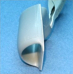
The next items to get attention were the engine intakes. Cutting Edge provides
the needed bulged intakes in the A-4F "Super Fox" conversion, which is a
required compliment to the A-4M conversion set. These intakes pieces are simple
replacements of Hasegawa kit pieces. After removing these pieces from their
casting blocks, I test fitted them on the model. I was dismayed to find them a
bit too small. A substantial step appeared in the outline of the fuselage where
the rear of the intake piece meets the fuselage.
After some study, I found the easiest way to fix the issue was to add a spacer
to the rear of the intake pieces. I pulled out some sheet styrene and laminated
a 0.015" thick piece of sheet styrene onto the intake piece. This eliminated the
step in the fuselage outline. The nominal increase in the thickness of the
intake splitter plate is not that noticeable. I informed Cutting Edge of this
problem, and they are verifying that their masters are good. They told me this
sort of thing is a sign that the molds are getting old and that they will fix
this for future production of the parts. The pictures below show the engine
intake with the spacer in place.
 |
 |
 |
|
Modified Intake - Front
|
Modified Intake - Inner Side
|
Modified Intake - Top
|
The outer walls on the Cutting Edge engine intakes are a bit thinner than the
Hasegawa pieces that they replace. This made the gap inside the intakes more
noticeable than it was with earlier builds of the kit I had done. Adding the
0.015" spacers further increased this gap, making it so I could not ignore the
gap. I carefully wrapped some 0.005" styrene sheet inside the intakes to fill
the gap. This was not perfect fix, but it makes the gap less noticeable when you
look back the intakes.
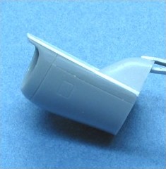
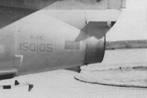
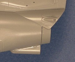
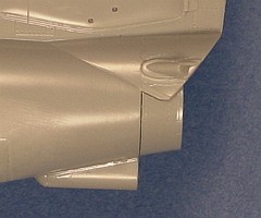
Another item I revised was the engine exhaust. Originally, when Hasegawa
released their Skyhawk kit, I investigated it and saw the two engine exhaust
pieces. I thought the short one was for the majority of Skyhawk versions and
longer one was the lengthened version used on the "Super Fox" A-4F and A-4M/N.
Now that I am actually building a kit that I know needs the longer exhaust, I
took a closer look at the kit pieces and at pictures of the real aircraft. I
have come to the conclusion that the exhaust on the "Super Fox" A-4F and A-4M/N
is not actually longer than the basic Skyhawk engine exhaust, but is marginally
wider at its opening. Consider the following pictures.
 |
 |
|
A-4E Exhaust
|
A-4M Exhaust
|
Note how both exhausts are the same basic length. Also note how the contour of
the areas is different at the lips. While the A-4E exhaust maintains a
uninterrupted contour all the way to the exhaust lip, the A-4M exhaust has a
flair in the lip to provide a slightly wider opening. It is amazing how long you
can look at something and not actually see what you are looking at. I rechecked
the Hasegawa instructions for the various Skyhawk kits and found they tell you
to use the shorter and longer engine exhausts on various versions. It really
helps when I read the kit instructions, not just browse them.
From what I can tell at this point, the shorter engine exhaust (as provided in
the Hasegawa kit) is for the A-4A, A-4B, and early A-4C. The longer engine
exhaust (as provided in the Hasegawa kit) superceded the short one at some point
on A-4C aircraft and continued on with all subsequent aircraft until the A-4M.
The "Super Fox" A-4F and A-4M/N have a third style engine exhaust that is not
provided in the basic Hasegawa kit. This new style is not hard to make, though.
I created one for my A-4M model by starting with the shorter kit exhaust and
attaching some strip styrene to the lip that extended it. I used 0.015" by
0.060" Evergreen strip styrene. I carefully rolled the strip to the approximate
circle size and attached it to the shorter kit exhaust with liquid cement. When
I cut it to length, it was a bit short, so I had to cut a small piece of strip
to fill a gap left at the point where the two strip ends were supposed to have
met. The following pictures highlight the change I made to the kit piece.
 |
 |
 |
|
Longer Kit Exhaust
|
Shorter Kit Exhaust
|
Modified Exhaust |
If you do not want to go to the trouble that I have gone to here on the engine
exhausts of your A-4M models, just use the longer kit engine exhaust piece,
unmodified. The difference in the final model is not really all that noticeable.
It is the kind of difference that only the person who built the model will see
in the final piece.
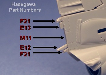
While I am on the subject of the tail area, the antennae configuration on the
trailing edge of the vertical tail changed with the A-4M as compared to the
A-4E/F. All the necessary parts are in the Hasegawa kit, I only needed to
consult some references to figure out which pieces to use a what locations. Note
that on early A-4M aircraft (and many A-4E/F), the spike antennae (kit parts
D19, E31, F21, and F22) are only fairings without the spikes. Close examination
of some pictures showed that there is a small rounded plug that covers the
mounting points of the spikes. I hacked off the spike antennae on the kit parts
and added small globs of super glue to represent the rounded plugs.
The image below (left) shows the correct early production A-4M configuration.
Note that this configuration was changed again for middle and late production
A-4M aircraft. Note also that while I point to where the formation light goes
(part M11), the actual clear part is not yet in place on the model.
 |
 |
|
Vertical Tail Antennae
|
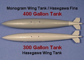
400 Gallon Fuel Tanks
|
The other image (above right) shows my work to create 400 gallon wing fuel
tanks. The tanks provided by Hasegawa are the 300 gallon size. While these are
correct for use on any Skyhawk version, the A-4M tended to more frequently use
the larger 400 gallon type. This provided a bit more fuel, and the higher
powered J57-P-408 engine could deal with the added drag.
The 400 gallon tanks were constructed using the tail fin assemblies from the
Hasegawa kit (the lighter gray plastic), mated onto the Monogram A-4 Skyhawk
wing tanks (the darker gray plastic). While I have no actual dimensions for the
size of a 400 gallon tank, the observed size difference between the Hasegawa and
Monogram tanks seems about right for what I have seen in pictures. I chose to
use the Hasegawa fin assembly because I liked its shape and details better than
the Monogram provided fins.
The rest of the conversion amounts to using alternate pieces already present in
the Hasegawa kit.
I used the small Hasegawa kit provided ECM antennae on either side of the engine
exhaust (parts D17 and D18). Early production A-4M aircraft did not get the
larger bulbous antennae provided in the Cutting Edge set (although they did
eventually get retrofitted).
I added the parachute brake housing under the rear fuselage
(parts D11 and D28). Note that the kit provides two different parachute brake
housings. The part numbers I list here are correct for the A-4M. The other parts
pertain to other Skyhawk versions.
A-4M Skyhawks do not typically have the flare/chaff dispenser on
the left side of the rear fuselage. They only seem to have the dispensers that
are on either side of the arresting hook. So, I used the rear lower fuselage kit
part with no dispenser molded into it (part A6).
|
 |
|
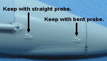
Right Side Static Ports
|
All A-4M Skyhawks use the bent refueling probe, so I attached
this (part E7) to the right side of the nose.
One thing not mentioned in the kit instructions pertains to the two static
points molded to the right side of the nose (small triangular shapes with raised
edging), just below and in front of where the refueling probe attaches. These
two items are mutually exclusive. You need to carve or sand off one of these
based on the type of refueling probe the aircraft has. Keep the rear static port
for aircraft with a straight refueling probe. Keep the forward static port for
aircraft with a bent refueling probe. Since I was using the bent refueling
probe, I kept the forward one and removed the rear one.
I constructed all the other antennae and details (not mentioned
here) to match what the Hasegawa kit refers to as "Scheme 2" (which is the
A-4F).
I chose to keep the weapons configuration minimal. I only built
up and attached the two wing fuel tanks. This was a fairly common loading for
the early years of A-4M usage.
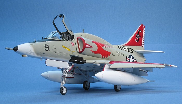
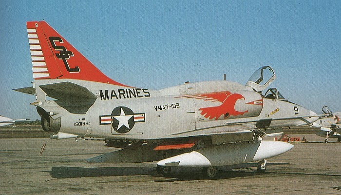
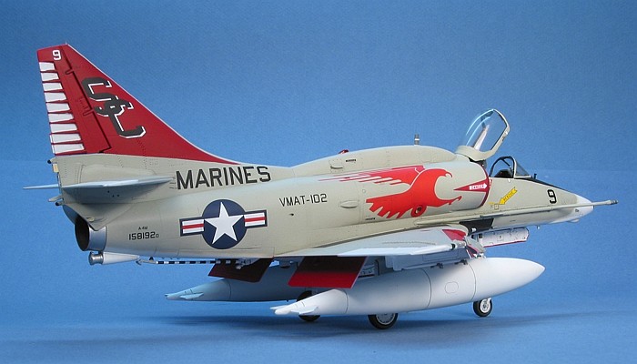
Cutting Edge provided lots of choices for markings on this model. Limiting
myself to an early production A-4M limited my choices down to only two of
Cutting Edge's options -- VMAT-102 and VMA-214. I have never been a big fan of
the "Black Sheep", and I really like the colorful VMAT-102 markings, so I chose
to go with the VMAT-102 aircraft.
Great kit -- great conversion! Some care must be taken to get
the fuselage cuts in the right places. With care, the conversion parts fit right
into the prescribed places. With the recent release of the Cutting Edge A-4M
cockpit update, it looks like I will be doing another A-4M in a late
production configuration in the coming months.
 Home
| What's New |
Features |
Gallery |
Reviews |
Reference |
Forum |
Search
Home
| What's New |
Features |
Gallery |
Reviews |
Reference |
Forum |
Search