|
Arado Ar 240A
by
Floyd S. Werner Jr.
 |
|
Arado
Ar 240A |

HML's 1/48 scale
Arado Ar 240 is available online from Squadron.com
Designed in response to the same 1938 RLM specification for an
aircraft to perform equally in the Kampfzerstörer and Aufklärung
role, the Arado 240 and Messerschmitt 210 would share similar experiences and,
ultimately, fates.
The Arado Ar 240 was a pressurized, twin engine, mid-wing
monoplane, that, like its contemporary the Me 210, was plagued by flight
instability. Both aircraft possessed an advanced feature in the form of remotely
controlled defensive armament enclosed within low-drag barbettes. Both aircraft
would be redesigned in an attempt to gain a new lease on life. Both the Ar 440
and Me 410 were equipped with more powerful engines. Each aircraft had its
fuselage lengthened and wings redesigned in order to solve their respective
flight instability problems.
Although Arado considered the aircraft ready for production at AGO
Oscherschleben, Erhard Milch cancelled the program in December 1942, sending all
completed pre-production aircraft to various Luftwaffe units. Ultimately, the
Kampfzerstörer and Zerstörer concepts were not viable in the face of
growing Allied air superiority, and the Ar 240/440 and the Me 210/410 were
relegated to reconnaissance duties.
|
MPM/HML Arado Ar 240
in 1/48 Scale |
The MPM kit contains approximately 60 molded light yellow resin
parts. Overall detail is crisp and panel lines are finely engraved. None of the
major pieces required any straightening prior to assembly. With one notable
exception, the surfaces of the parts were defect-free. My example had a slight
imperfection running the full length of the upper fuselage seam. Kit decals were
well registered but appeared a touch thick.
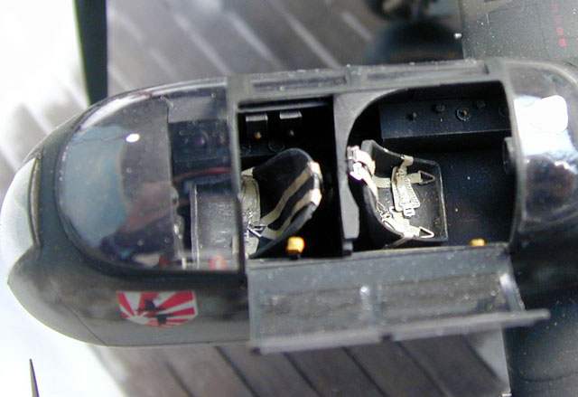
Cockpit
The cockpit tub was molded as a single piece containing the seats and sidewalls.
Rudder pedals, control stick, gunsight, and throttle levers were added to the
tub. After the subassembly was sprayed with Floquil Primer and allowed to dry,
it and kit part PUR 32 were sprayed with Floquil RLM 66 enamel (including the
bottom). Weathering was done using a light wash of thinned black artist’s oil
paint followed by a light dry-brush treatment with RLM 02. As interior detail
shots of the Ar 240 were difficult to find, a little artistic license was
required. Fine Molds photoetch seatbelts were bent to the desired shape and
painted with Polly-S Dirty White. Once dry, the paint was scraped off the
buckles with the tip of a sharp #11 X-Acto blade to expose the silver beneath.
Various cockpit and instrument panel details were highlighted with RLM 04 and
23. Additional highlights were achieved using a silver pencil.
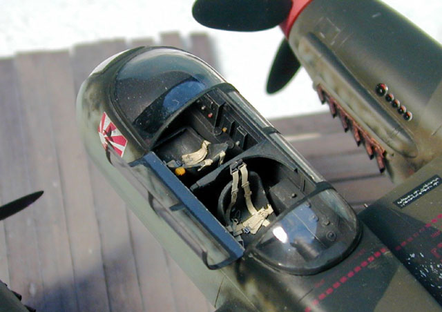
The instrument panel lacked detail, as the dial faces were simply represented by
featureless depressions. To bring some life to the area, the panel was sprayed
flat black and then drybrushed with neutral gray. Various “spare” instrument
decals were applied inside the depressions. The glare shield, also painted flat
black, fit very well over the panel.
Don’t forget to add part PUR 32 under the cockpit assembly in order to prevent
one from seeing “through” the model.
Fuselage
The cockpit and tail wheel well sidewalls were primed, sprayed with Floquil RLM
66 and dry-brushed with RLM 02. The completed cockpit subassembly was attached
to the right fuselage half using cyanoacrylate glue (CA).
I drilled out the bottom of the tail wheel strut and inserted a brass tube. The
brass tube provided strength to the resin strut and allowed the tail wheel to be
mounted in a “swiveled” position. After it was painted RLM 02, the tail wheel
assembly was added. Take care to insure the strut “sits” properly after the
fuselage halves are mated. The tail wheel access area could be improved with
additional scratchbuilt detail.
Fuselage halves were mated using CA. Overall the fit was fair. In order to
remove the imperfection mentioned in the kit preview, I “filled” the fuselage
seam with a mixture of resin shaved from the pour gates (cut into very small
pieces) and CA. Because this “filler” was resin, it sanded down easily,
feathered and ultimately scribed just as easily as the kit surface.
After the fuselage seams were dressed, replacement periscopes made from
Evergreen 5/32” styrene tubing were applied. The barbettes were left off at this
point.
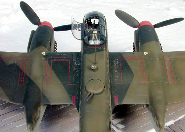
Wings
Individually cast as solid pieces, the left and right wing halves were extremely
straight and required little clean up on the leading edge. To insure the
wing/fuselage joint had adequate strength, I reinforced it by inserting three
1/2” long pieces of 1/16” brass rod. The wing-to-fuselage joint was nearly
perfect and required very little filler.
Engines/Nacelles
The engine nacelle assemblies consisted of four parts--left and right halves,
forward and aft blanking plates. NOTE: I assembled the aft portion of the
nacelles as the instruction indicated but these were too narrow when applied to
the wing. The nacelle was cut at the top and spread using Evergreen strip
styrene, taking care later to fill the upper wing to nacelle joint. The nacelles
attach to the wings perfectly and required just a touch of putty around the
front and back. Strip styrene and tubing details were added to bring some life
to the main gear bays.
The air intakes for the DB601 engines were cast as a separate piece—be careful
as they are thin and very fragile. I added mine at this time. Replacements for
PUR 44 (radiator intake supports) were made from Evergreen 0.010” sheet styrene.
Kit exhausts were left off at this point because Moskit thin metal exhausts
would be used later.
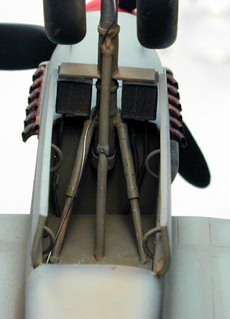
Tail
Each of the vertical stabilizers had some minor pinholes which were filled using
CA. The vertical stabilizers were “test fit” to the horizontal stabilizer. After
minor cleanup afforded a satisfactory fit, a small 1/32” hole was drilled into
each end of the horizontal stabilizer and a short length of 1/32” brass rod was
inserted into each end for strengthening the joint. After careful alignment, a
1/32” hole was drilled into each vertical stabilizer. Each vertical stabilizer
was gently “pressed” onto its pin, and carefully adjusted to achieve proper
alignment. Once aligned, a few drops of ultra thin CA were carefully flowed into
the joint.
Once proper alignment of the horizontal stabilizer was obtained I added a drop
of CA and dressed the joint with a kiss of filler at the front to fair the tail
surfaces together. The directional control fairings were added next using ultra
thin CA. Caution must now be exercised when handling the model as the fairings
are very fragile. I attached mine after the tail wheel was added.
 Landing
Gear Landing
Gear
The resin landing gear would, ultimately, require reinforcement as well. A small
hole was drilled into each strut as far down as possible. Brass rod was inserted
and held in place with ultra thin CA.
I drilled through the axle to attach to wheels.
I had to replace the radiator mounts with items made from
styrene. I built up the radiators with some Detail Masters Adapter #2 and some
0.025” fly fishing lead weight. This captured the unique look of the radiators
and added to the interest of the landing gear.
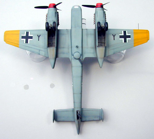
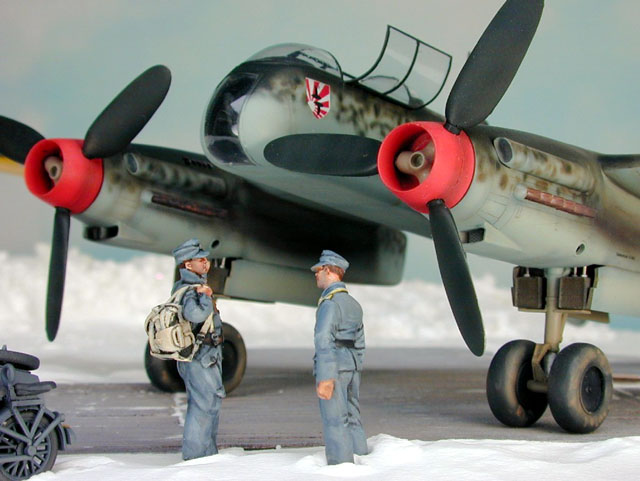
Propellers
The propellers of the Ar 240 are unique because the hubs were visible through
the spinner hub. MPM/HML captured the look exactly.
I drilled tiny holes in the base end of each propeller blade and
in the hub, inserting a small wire in this joint for additional strength. I also
used telescopic tubing for the spinner and nacelle to allow the props to be
installed.
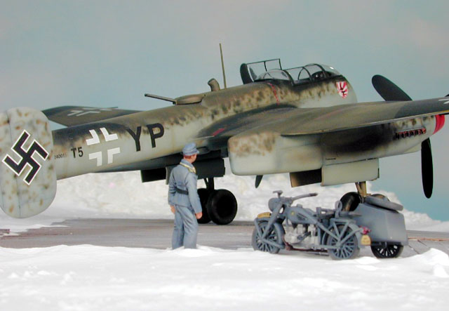
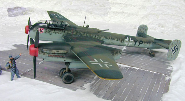
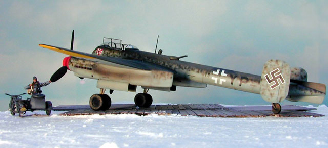
After careful examination of the limited number of reference
photos available, I interpreted the camouflage scheme of T5+YP as RLM 65/70/71
with mottled RLM 70/71. I KNOW this goes against conventional wisdom that
suggests RLM 74/75/76, but that’s how the colors appeared to me. I also
interpreted the spinners as RLM 23.
The model was washed with a solution of Dawn dishwashing detergent to remove
mold release agents and/or finger oils, wiped clean with a lint free rag and
left to dry overnight. A coat of Floquil Primer was applied and any flaws were
fixed. Panel lines were preshaded with Floquil RLM 66.
Floquil enamels were to be used on this kit. I liked their interpretation of RLM
71Dunkelgrün and 65 Hellblau but was not impressed by their interpretation of
RLM 70 Schwarzgrün as I felt it to be too black.
I preshaded the panel lines with RLM 66. RLM 04 was sprayed for underwing
identification markings. Once dry, I masked these areas and sprayed RLM 65 on
the undersurfaces. The wing leading edge was masked to provide a hard edge for
the upper camouflage colors. Dunkelgrün was sprayed across the upper surfaces of
the aircraft, including the fuselage mottling. Masking off the camouflage
pattern per kit instructions I sprayed the Schwarzgrün. Different references
indicate different splinter patterns so it is your choice which pattern you
select. Although Floquil RLM 70 is very black it provided a nice contrast. I
lightened up the colors and sprayed areas in a random pattern to add depth to
the colors. While the airplane was drying I painted the prop hub RLM 02 and then
masked it off and painted the spinner RLM 23. The effect is a very nice looking
airplane.
Letting this dry for a day, I sprayed a few coats of Future acrylic floor polish
over the entire model in preparation for decal application.
As a general philosophy, I use kit decals whenever possible.
While these reacted moderately well to setting solution (Mr. Mark Softener) they
still silvered and did not snug down as well as I had hoped. The wing walkway
decals were so thick it was difficult to see the panel lines beneath them! I
replaced the kit swastikas with ones from the Aeromaster “Swastika Sheet”. It is
interesting that the Hakenkreuz was very large on this airplane. Once everything
had dried I very carefully painted over the decal film that silvered. I used low
tack Post-It Notes as a mask to avoid damaging any decals. Again, in perfect
hindsight, I would recommend aftermarket decals wherever possible.
The kit does not provide any detail (raised or decal) for the engine mounted
instruments. I represented this using decals from Superscale sheet for the Hs
129. I cut the large dials from the sheet and placed them in front of the
smaller instruments. Not perfect, but convincing.
After drying overnight, decals were sealed with a final coat of Future followed
by a coat of Polly-S Clear Flat in preparation for weathering.
Weathering began with application of diluted Burnt Umber artist
oils into the panel lines. This wash was very light, except on the undersides
where dirt would collect. The extent of weathering is highly subjective, at best
a personal choice. A slight heavy wash was applied as the effect lightens when
oversprayed with clear flat.
I chipped the paint by tapping a silver pencil or two against the leading edge
in no particular pattern and at various angles. A silver pen was then applied
and smeared with a cotton swab. This effect, too, is muted by the clear flat
overspray, so “a little extra” is OK. I also “chipped” certain panels using the
pencil.
A small amount of dark brown pastel was applied to the model and the color
“dragged” with a cotton swab over the surface where the exhaust staining would
occur. I prefer using cotton swabs that have a small pointed end for application
and a larger one for blending (found in beauty shops). Once the basic outline
was established I applied a highly thinned mixture of dark tan and flat black
paint. Before you clean your paint cup add some more flat black and build the
color up carefully. One final touch is to add a hint of orange pastels to the
area around the exhausts themselves. Blend this in the direction of airflow with
a cotton swab.
The wheels were dabbed with some dark tan and then lightly airbrushed with dark
tan onto the tire itself and added the area where the mud would be slung on the
back of the nacelle. Seal the whole weathering process with a coat of clear
flat.
I tried something a little different this time and touched up the paint in spots
with the color out of the bottle without putting a flat coat over it. I liked
the results and will definitely use it again.
|
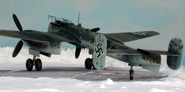
Canopy and Finishing
Touches |
Thankfully, two canopies and two chin bubbles are supplied. This
allows some practice and margin for error. One of my chin bubbles was damaged
while in the box - my fault not MPM’s. After the vacform canopies were cleaned
up, they test fit “too narrow”. I decided to display the canopy up because I
could get the front and back to fit properly but not the center.
The forward chin bubble was more difficult to fit and it had to be more precise.
Carefully cutting it from the plastic was not difficult, I was worried about
damaging it because it was so thin. Once all the clear parts were removed I
dipped them in Future acrylic floor polish and let them dry overnight. I then
masked with Tamiya tape, filled in the center with Gunze Mr. Mask, painted and
finally weathered the canopy.
To attach the canopy I squeezed it to get it to fit properly and then set it
with CA and accelerator. If you do this carefully it won’t fog the windscreen. I
filled around the canopy with Elmer’s White Glue and when it dried I used
Post-It Notes to mask the area for painting.
The antenna was attached with CA. I could not determine from my reference
pictures the proper location for the antenna leads so I left them off. I used
Micro Krystal Kleer for the periscopes and built it up in layers to get the look
I was after. I also used it for the navigation lights on the wing tips and tail.
Moskit thin metal exhausts for the Me-210/410 were a little too large so I cut
the base right at the last exhaust stack. The whole base assembly was sanded
down to allow them to fit the openings in the nacelles. Some sanding of the
exhaust area was necessary using riffler files. The Moskit exhausts added a lot
of realism to the kit.
This was my second “all resin” kit and I recommend it to anyone
willing to pay the price of the kit, originally around $80. It is an interesting
airplane. However, there is very little reference material for the type, the
best being the Gerhard Lang books from Schiffer. There are some unique pictures
in the book by William Green also.
|
Aftermarket Resources |
|
Moskit Exhausts, 48-04
|
|
Fine Molds Luftwaffe Seatbelts |
I enjoyed construction of this, my second “all resin” kit very
much. There will certainly be more MPM/HML kits in my future. MPM/HML provide a
fairly accurate kit of subjects that other manufacturers will not produce in
injection form. The largest single drawback to this kit in my opinion, was the
mediocre quality of the decals. Although you will need or want to add some
additional detail, the kit is a very good basis to start from. The Moskit
exhausts and the Fine Molds Seatbelts represent very nice after market additions
that will add alot of character to this unique airplane. I recommend these
aftermarket resources for any kit they are designed for.
-
Warplanes of the Third Reich; Green,
William; 1970, Galahad Books, NY, NY, ISBN: 88365-666-3
-
The Luftwaffe Profile Series No.8
Arado Ar 240, Lang, Gerhard; 1996, Schiffer, Atglen, PA, ISBN:0-88740-923-7
-
Flugzeug Profile Arado Ar 240, Lang,
Gerhard: 1989, Flugzeug, Illertissen, Germany
-
German Aircraft Landing Gear,
Sengfelder, Gunther, 1993, Schiffer, Atglen, PA, ISBN 0-88740-470-7
Click the thumbnails below to view
larger images:
Model, Images and
Article Copyright © 2002 by Floyd
Werner
Images Copyright © 2002 by Alan Del Paggio
Page Created 01 Januray 2002
Last updated 04 June 2007
Back to HyperScale Main Page
Back to Features Page |
 Home
| What's New |
Features |
Gallery |
Reviews |
Reference |
Forum |
Search
Home
| What's New |
Features |
Gallery |
Reviews |
Reference |
Forum |
Search