|
1/48 scale
scratch built
1918 Curtiss MF
Seagull Flying Boat
by Michael Robinson
|
 |
|
1918 Curtiss MF Seagull Flying Boat |

HyperScale is proudly supported by
Squadron.com
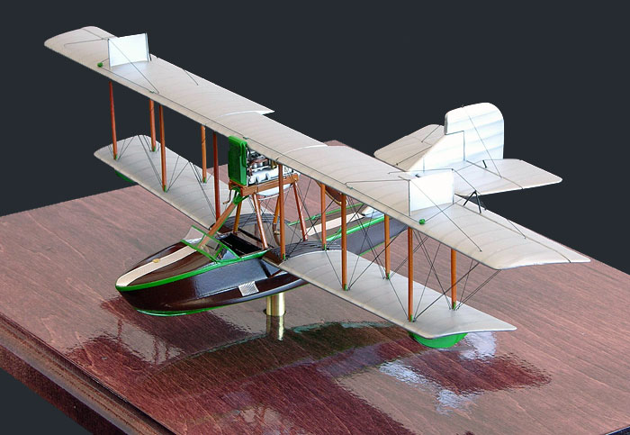
This is my 1/48 scale
scratchbuilt model of a 1918 Curtiss MF (Modified “F”) Seagull, as
produced right at the end of World War 1. The MF Seagull was a more
“upscale” civilian version of the US Navy MF Boat. Differences were a
better finish and wooden slat seats instead of solid boards (wow big
difference there). Only about 50 were completed and sold, due to the
number of surplus MF Boats being sold at the end of the war.
This particular subject
is modeled after the MF on display at the Canadian Air Museum in Ottawa
Canada. Altogether about 200 hours over 4 months were spent during
construction. I’ll give a brief overview of the construction techniques
I used, and you’ll see that nothing out of the ordinary was used, just
simple, basic scratchbuilding as shown by Harry Woodman in his book
Scale Model Aircraft in Plastic Card.
Fuselage/Hull
The Fuselage master was
carved from basswood, then the sponsons were added and carved separately
before vacu-forming. I thought it would be easier to add them after,
rather than to try to carve them out of a solid block of wood. The
master was cut in half down the centerline, and vacu-formed using .030
plastic. Seats, floor slats, instrument board, and side panels were
fashioned from .010 and .20 plastic sheet cut into strips. The control
column, steering wheels, rudder bars and supports are from .020 brass
wire and bits of left over PE soldered together. Instrument faces are
from Reheat decals, with bezels from Foto-Cut and left over bits from
Copper State Models gage sets, and all control cables are present for
aileron and rudder and elevator controls. The “headache strut” running
to the engine pylon contains the Bowden cables and electrical wiring for
the engine, and these are represented by fine copper wire and metallic
thread. The windscreen is vacu-formed clear thermoform, and was
installed at the very end of construction. The walkways on the bow and
aft of the engine are heavy duty aluminum foil that was embossed over a
fine gage screen. It was then cut into strips and glued in place using
Micro-Scale Metal Foil adhesive. The windscreen framing was made in a
like manner, but painted green before installing. It was left aluminum
on the backside as the inside framing is not painted. A .010 center keel
board was glued onto the bottom edge of each half before gluing the
halves together, and then sanded to final profile. To square up all the
edges, .060 Evergreen Angle was cemented to the tops and along the ends
of the hull steps. These were filled with CA and blended in to “sharpen”
the soft corners of the vacu-formed hull. Along the top edges of the
hull, they were left in raised relief as the real aircraft had aluminum
reinforcing edges. The cover over the Fuel tanks under the engine pylon
is a section of .010 plastic cut to shape, with .010 x .010 plastic
strips for the raised walkways. A brass PE bit represents the fuel cap.
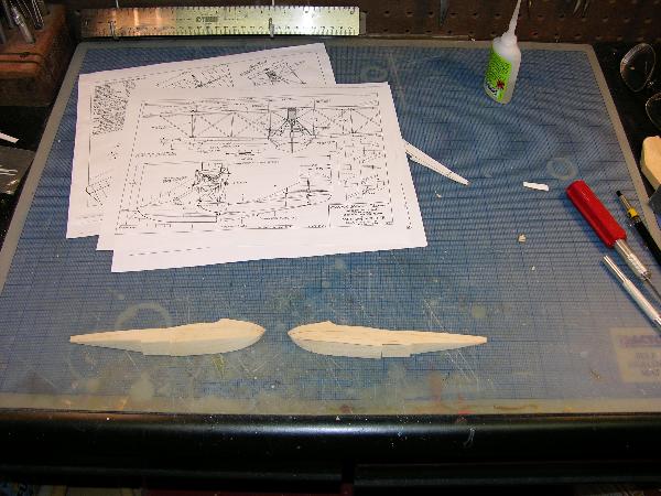
Picture 3 Hull halves before installation of sponson blanks.
Click the thumbnails below to view larger
images:
[../../photogallery/photo00031556/real.htm]
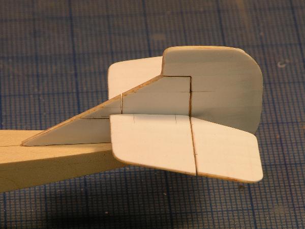
Picture 4 Completed hull master after sponsons were sanded to
final shape.
Picture 13. Hull halves after vacu-forming.
Picture 14 Hull structure and interior going in. Slat floors,
seats, and instrument board are all from .010 plastic. Stringers are
.005 strip, and bulkheads are .030 plastic. 1/8th square
plastic acts as reinforcements and something to glue bulkheads to.
Fuselage is very light but also very strong.
Picture 15 I made a test strip to try different shades of
paint to simulate the mahogany. I finally settled on my own mix, with a
Tamiya Clear Orange overcoat.
Picture 16 Shot of the interior fittings before being
painted. Brass wire, bits of leftover PE and plastic strip make up the
controls and seats. The ruler gives an idea of the size of the parts.
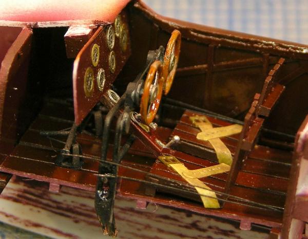
Picture 17 Shot of the interior before everything was closed
up. Much of it became lost to sight when the hull halves were joined,
but I know it’s all in there.
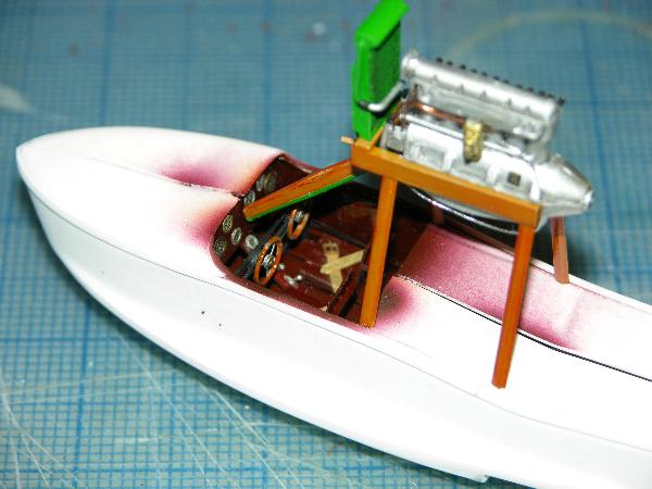
Picture 18 The Engine pylon is being test fitted, and
locating holes for struts are marked out and drilled.
Wings
Both top and bottom
wing began life as Lindberg Jenny wings, and were modified to correct
chord and outline, and sanded smooth to remove all rib detail. I then
trimmed 1/16th of an inch from the lead edge so the chord is
correct. It took two kits to get the number of blanks needed. I used
two for each upper wing and three for the lower wing and upper wing
center section. Two fillers had to be added to the kits upper wing
cutout to make them rectangular in shape. These are illustrated in the
picture below. Once the blanks were done, they were re-sheeted with .005
plastic with the ribs embossed from underneath. Once covered and sanded
and filled, the ailerons were cut from the upper wings and hinged with
brass wire. Strut locating holes and rigging attachment points were
plotted out with a square and a rule, and all holes predrilled. A total
of 12 wing struts, and 4 engine pylon struts were made from correct
width Contrail Strut material, with Part PE turnbuckles cut in half and
glued on all ends to represent strut fittings. These were cut to length
as the model was fixed to an assembly jig so the lengths would be
correct. The aileron control “tripods” are soldered together from .020
copper wire, then painted black before epoxying into place. Lower wing
tip floats were carved from solid 1/8 plastic, with planning skids added
from .020. The Anti-Skid plates on the upper wing are from .005 plastic,
with .020 brass wire for the struts. All struts were drilled on the ends
for .020 copper wire to reinforce the attachment.
Click the thumbnails below to view larger
images:
[../../photogallery/photo00000081/real.htm]
Picture 5 This shows the upper wing blanks with the “plug” to
fill the notch in the Jenny upper wing.
Picture 6 This illustrates how I emboss the ribs from the
backside of the skin. Nothing more than a strait edge, a blunt scriber
and pre-measured locating marks.
Picture 7 Here are the finished wings prior to painting. The
yellow plastic of the blanks can be seen on the lead edge. The skin is
sealed with CA along the edge, then sanded and fared into the plastic
blank.
Tail Surfaces
The tail surfaces are
carved from 1/16th basswood to an airfoil shape, then skinned with .005
plastic, same as the wings. The ribs were embossed on the underside of
the card before gluing onto the cores. Once covered, the elevators and
rudder were cut loose and hinged with brass wire. Control horns were
added from .020 copper wire, flattened and filed to correct shape.
Click the thumbnail below to view larger
images:
[../../photogallery/photo00018218/real.htm]
Picture 9 Same technique was used for the Fin and Rudder.
Sealing the edges of the basswood with CA “plasticizes” it and allows
it to be sanded and blended into the skin just like plastic.
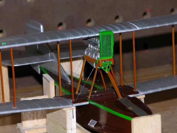
Engine
A Curtiss C6 engine was
used to power the Seagull, as opposed to the 150 HP Hispano Suiza used
by the military MF Boats. No kit engine exists of a suitable Curtiss C6,
and there is very little information, save for one fuzzy photograph I
had that showed the basic outline. The Curtiss K6 was derived from the
C6, so I used it as a guide, making the notable differences of one piece
cylinders and block cast as one unit, and both spark plugs being on one
side of the cylinder head. Other than that there were few differences
externally. The engine is made from blocks of .060 and .080 plastic,
sections of 1/8 plastic tube, and various bits of solder and wire. All
plumbing, ignition, throttle and fuel lines are present, as well as oil
breather at the bottom of the oil pan. The prop is carved from laminated
basswood and rosewood, stained and then Bare Metal gold foil added for
the brass leading edged. Prop hub bosses are from Foto-cut, with bolts
and crank added from fine wire and solder. The pylon is .060 plastic and
Contrail Strut, and the radiator is made from 2 .040 sheets glued
together with a header tank from a bit of reshaped strut material. The
radiator faces are from a section of material cut from an old pair of
pantyhose (with wife’s permission of course).
Click the thumbnails below to view larger
images:
[../../photogallery/photo00007440/real.htm]
Picture 10 Basic block before any details were added. only
kit part used was the snout from the Jenny OX5.
Picture 11 More goodies added. Magnetos, camdrives, and
beginnings of exhaust and intake plumbing.
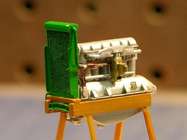
Picture 12 Completed engine in pylon with ignition wiring,
radiator, cooling lines, carb and intake and water pump added.
Assembly and Painting
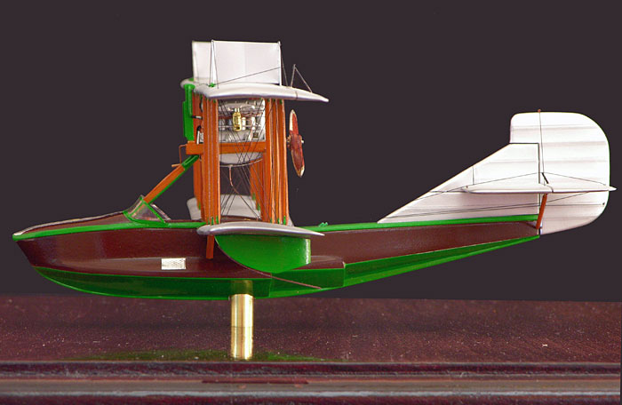
 The model was painted
with Model Master Willow Green for all the trim and hull bottom. The
Mahogany shade is my own mix of red and brown, with an overcoat of
Tamiya Clear Orange to give it a varnished look. The model was painted
with Model Master Willow Green for all the trim and hull bottom. The
Mahogany shade is my own mix of red and brown, with an overcoat of
Tamiya Clear Orange to give it a varnished look.
The struts are painted
with a light Tan Acrylic, also with a clear orange overcoat. Wings and
tail assembly are painted with Pactra Aerogloss “Silvaire Aluminum”
Dope, and the engine is painted with various shades of Model Master
Mettalizers.
Everything was overcoated with either clear Future for
gloss, or Dull-Coat for the semi-gloss areas.
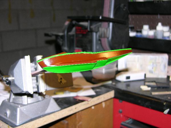
Picture 19 Hull right after painting - the green isn’t quite
so “loud” on the finished model. The camera flash really enhanced it.
Assembly was done the
same as a basic kit. The fuselage halves were joined first, then lower
wings added. The model was then secured to an assembly jig, top wings
rubber banded into place, struts cut to length and then tail assembly
installed. All rigging for upper wing was set in place before final wing
installation, and then each strut was epoxied in place, one at a time,
until wing was secure. Rigging then commenced form the inside center
and worked outward, doing each line one at a time until all was
complete. Rigging material is .006 nylon monofilament, set into holes in
upper wing and then poked completely through predrilled holes in bottom
wing. They were then drawn tight with a pair of tweezers and CA’ed in
place. After all were secure, the excess was trimmed off and decal
circles were applied over the holes. They represent circular inspection
panels at each strut location. There are 208 decals on the model. Each
wing and tail rib has a strip applied over it to represent wing tapes
and rib tapes. These were all applied one at a time until all were
covered, then sealed in Future.
Click the thumbnails below to view larger
images:
[../../photogallery/photo00022208/real.htm]
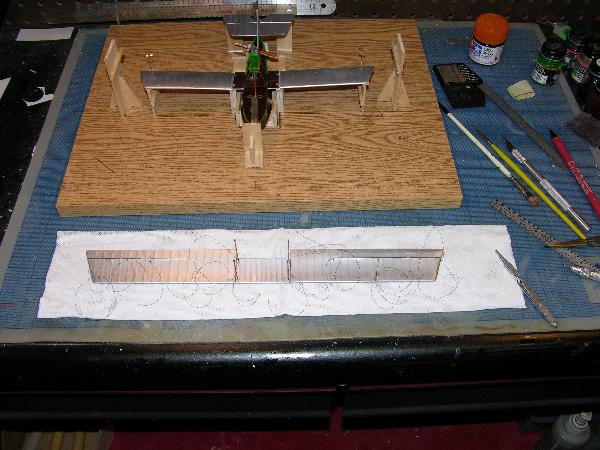
Picture 20 The model sits in a jig after final painting,
ready for final assembly.
Picture 21 Top wing after being jigged in place. The rib
tapes really stand out here as the wing hasn’t been overcoated or sealed
yet.
Picture 22 Here the struts are being measured to fit, and the
engine pylon has been rigged before the top wing was permanently
installed.
Picture 23 Here the rigging is preinstalled into the top
wing. It is then pulled taught through holes in the lower wing, seized
off with CA, and trimmed flush with wing. The holes were then covered
with 1/8th” circles of silver dope painted decal to hide
them.
Base
The base is solid
basswood with a mahogany stain, and the model is mounted on a single
brass support. This allows the model to be spun on the base for
inspection without having to pick up or move the base.
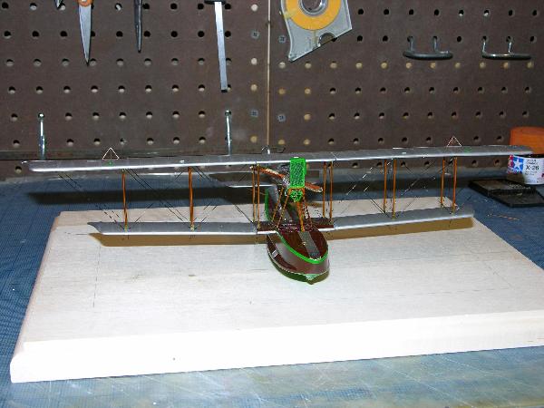
Picture 24 The rigging is finished and base is cut and ready
for staining.
Thanks for looking.
Click the thumbnails below to view larger
images:
[../../photogallery/photo00026857/real.htm]
Model, Images and Text
Copyright © 2007 by Michael Robinson
Page Created 31 October, 2007
Last Updated
24 December, 2007
Back to
HyperScale Main Page |
 Home
| What's New |
Features |
Gallery |
Reviews |
Reference |
Forum |
Home
| What's New |
Features |
Gallery |
Reviews |
Reference |
Forum |