|
Tamiya's 1/48 scale
F4U-1A Corsair
by
Hubert Ortinger
|
 |
|
Chance-Vought F4U-1A Corsair |

Tamiya's 1/48 scale F4U-1A Corsair is available online from
Squadron
Zinc-Chromate
Everyone who is interested in airplane model construction has surely
already certainly encountered the designation of zinc chromate. In order
to understand what ZCh. means in connection with the interior color of
US airplanes one must first know what ZCh is, and what it was used for.
ZCh is a resistant coating against corrosion, which was and/or still
becomes attached via different paint applications. Its highly toxic
composition protects the (metal) surface against damage and corrosion by
organic materials and provides a subsequent galvanizing.
Developed by the automobile industry, it was used from 1933 in aircraft
construction. At that time ZCh does not have a meaning as a color to
separate, rather as an undercoat and protectant. In crystalline form ZCh
has a bright greenish-yellow clay/tone and this color is emphasized if
it is mixed with a carrier. This mixture offers the basis for a
translucent painting, which was laid on usually in only one thin coat.
As a consequence, the coated surface has an influence on the finished
appearance. That means: on white/bright undergrounds ZCh appears rather
yellowish, on metals and dark surfaces rather greenish. Color additives
were also applied to change the resulting finish. In the direct prewar
time and initial phase of the war the pure base mix was usually used. To
make a more opaque and a more durable protection for fast wearing parts
and surfaces, it soon became common to add black lacquer whereby the
color became green. But there is sufficient proof that airplanes
exhibited different painting in different parts. For example light
yellow wheel housings, apple-green weapon bays and green cockpit. At
Vought even a pale-pink clay/tone existed, developed by the additive of
red color labeled “Salmon” was used as a method to indicate the second
coat.
While ZCh, technically seen, represented an effective corrosion
protection, the untinted finish was impractical for crew areas. The
garish interior painting coupled with the underlying metal dazzled the
eyes. This led to the use of different tinted green tones in cockpits
and other crew areas. In the year 1943 the name cockpit-green emerged in
the ANA (Army/Navy/Aircraft) agreement for the first time, whereupon the
Navy standardized the zinc chromates/black–mixture and starting from
1943 the designation ANA611 Interior Green. From then on it was the
colour used in all crew areas. After the war this color became official
for complete interior painting.
Nevertheless, it was quite normal for the lower surface colour and/or
light-grey to be used for the wheel housings and even the interior of
the engine compartment / cowling.
My Project
After I already outdone myself with my Wildcat with folded wings and
superdetail set, I intended to do the same with this Corsair, so I
wanted to detail the cannon bays and folded wings. However, since every
renowned modeler has already built “common” F4U, I wanted mine to be
somewhat special and unusual.
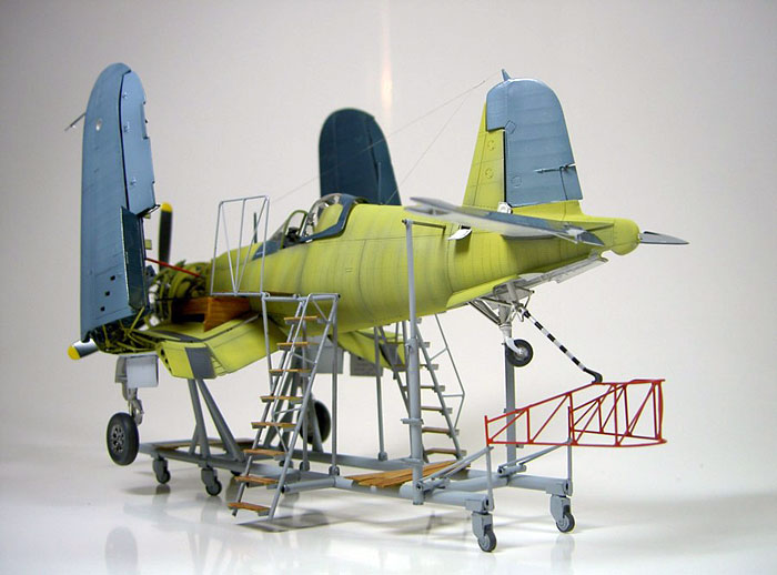
My decision was to depict an incomplete airframe on the assembly line
based on a photograph in the Squadron publication „Corsair in Action “.
But how I should build the factory assembly jigs?
The Assembly Jig
First I made various sketches on 1:48 copied side tears and searched
on innumerable photos for the exact „Jack here “position for jacking up
on the lower surface. After many unsuccessful attempts I finally had the
brilliant idea and it succeeded me to make the rollers out of plastic
sheets different strengths, and that six times, because I did not have
notion from pouring off.
Enormous amounts of plastic profiles were blended until finally I
“welded” the frameworks including the beams with “superadhesive“. A
model of the same type built in former times had to help me finding and
plumbing the correct gauges.
I strengthened the basis framework with a metal tube because the weight
of the airplane and the emphasis of the finished model had not to be
underestimated for safety's sake. Also the gauges of the platform
placeing on the wings had to be designed and estimations were determined
and then carved and glued from Sheet.
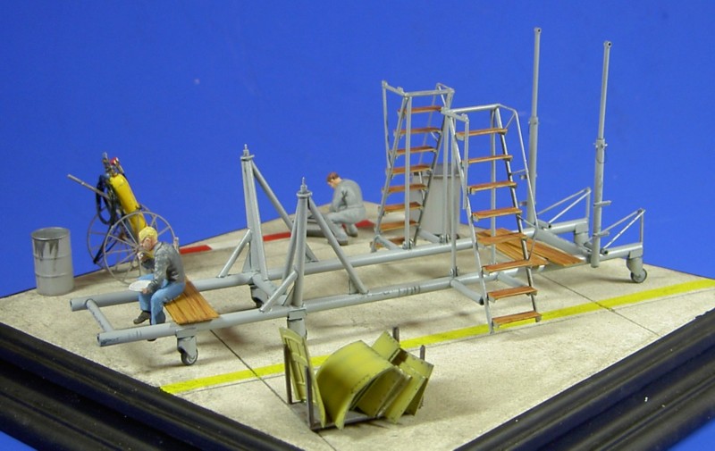
I soldered the hand rails of the steps, the railings of the bridgework
and the safety loop for the tail from curved brass wire. A unobtrusive
wood structure of the appropriate parts was depicted by pulling over
sandpaper.
I sprayed everything in semi gloss grey from Revell whereby I lightened
the longer pipes centrically and all welding seams became a whashing.
Descrete lacquer damage at some corners and edges were up-painted in
dark grey to give a used look.
The safety loop was painted red. For the wood grain I looked myself to
the WW I modelers, who use this technology with their flying cases. The
parts for it were primed with the colours sand and skin. After
sufficient drying time I took brown Oils and painted with an old brush a
rough wood structure on it which I wiped off after a few minutes with a
rag dampened with lighter fluid again.
Sounds easy - is also easy!
As the result turned out too little in the comparison to the airplane
high-contrast I later repeated the whole procedure with Vandikbraun once
again.
The Corsair
I began to install with the wing areas, the most important section
for me, because I wanted the wings not only folded but standing
perpendicularly to view both onto the folding mechanism and onto the
weapon bays. The Tamiya hinge arrangement for this option was incorrect
for it however both the Resin wheel wells and Resin weapon pits had to
be inserted in the way stood to a large extent uselessly there. The
intersection had to become completely grind and the mechanism had to
construct as well as the hinges from Evergreen material. As I did not
know to lend sufficient stability to the whole construction at this time
yet I considered, but for me was clearly that I would have to strut it
like the original.
The special fittings of Aires fit perfectly after the necessary place
for it was milled out and the appropriate portions (flaps) were sawn
out. For setting in the MG´s easily and becomming a more beautiful
transition of the openings at the wing leading edge I used suitable
plastic pipes. The ailerons and also all other control surfaces were
naturally sawn out and exchanged against their-same by Aires.
Additionally still all trim tabs were also modified. After I inserted a
fodder and the hinge mockups to conceal the view into the inside the
wings could be stucked. The position lamps at the wing ends were sawn
out and replaced with transparent plastics. The clunky pins on the
landing flaps which are attached separately in the kit were filed off
and I fastened them only to the joints and small bits wire. However
that´s sees not completely so stable for it but failed more filigree and
more original-faithfully.
The holes at the wing had to be closed then with plastics. By the
catapult heels I was not inspired - I cut them off and made it scratch.
At all everywhere something was filed and replaced and probably there
wasn´t many parts which were not changed and detailed in any way!
With the cockpit for example (a real gem), I wanted to be able to look
better inside so the seat had to developed. The seat basic stand is
stupid-proves cast on and must designed for my requirements and adapted
to the rear former.
The engine is a kit for itself but nevertheless required still much
proactive. I added the ignition cables with thin fishing line and
detailed the ring which lead them to the cylinders and keep them away
from their heat at the same time. Painting the unit took place on the
foot and turned out rather difficulty because the exhaust manifold
unions was glued already there. Still to mark is that I had not to lose
it at no time from the eyes that I finally wanted to represent an
airplane fresh from the factory which the thing made still more
complicated.
It means low key weathering!
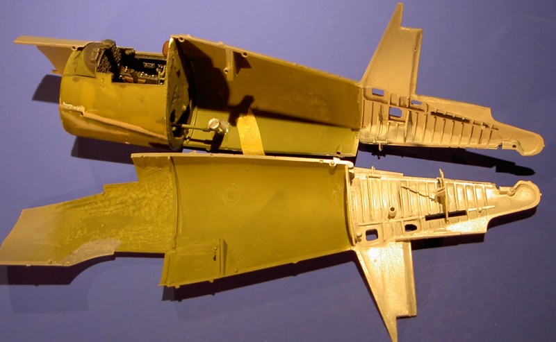
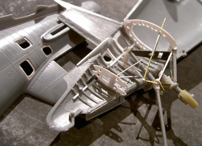
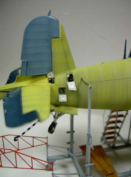
Until I was allowed to stick the trunk halves passed still much time I
also wanted the servicing covers for the tail landing gear opened there
and therefore copied the complete drawing in mechanism for this. I
prepared the construction in such a way that I had only to insert it
after painting. I did not replaced the acceptable tail landing gear
doors, but however detailed a model-fair closing mechanism.
In the pictures one can recognize the claimant expenditure better
than I can seizing it into words.
Occasionally I also employed with the main landing gear that required
exactly the same much attention by myself. Tamiya plans a loaded
chassis, but however my airplane hangs in air why I had the chassis leg
to show extend. In addition I first cut off the feather/spring shears,
replaced the absorber pistons by a metal pin, and stuck her far opened.
Also the mechanics on the front, which turns the wheel when drawing in
by 90 degrees is missing at the kit chassis and should be added. The
wheels seemed to me too thickly, why I divided, filed them thinner and
again stucked them together. There was no profile thereafter so I
decided somewhat to try out which I had frequently seen:
I painted the wheels anthracite coal, masked a groove profile and dry
painted with becoming bright grey at all. An amazing effect adjusted
itself!
At the separate rims I sanded so much away until the plastics between
the spokes discharged. Although the plastic parts of the kit for the
drawing in mechanism of the main landing gear are not bad but did not
fit with the model-fair linking in the Aires resin landing gear well.
Away with it! The reconstruction looks still more filigree. Over
stability I did not had to think!
Rosie the Riveter
Recently I bought “Rosie the Riveter” and finally decided to try it
out. Before I joined the fuselage halves I studied the airplane surface
and marked with a pencil, guided by model photographs, a little logic
and something imagination the structure of the rivet rows on the model
surface. I practiced handling the new instrument on cast-off parts until
I was finally ready. I applied the handle with light pressure following
the lines. The very much time-consuming occupation requires
concentration, above all at milled places the plastics was very thin or
with splices, which burst with too much pressure gladly again. For
several hours I did nothing else as to holes my model.
I did not think I was able to manage “stressed skin” on sheet metal ,
which was to be hurt however the original surface was anyway rather
smooth to owing the new spot welding procedure.
After sanding with finest Flies I was allowed to finally stick together
the trunk and with lower part. On the inside I still detailed the flap
for the compressor cooling before inserting the fire wall with the oil
tank.
At this frame now also the attachment for the struts to support the
outer wings in folded condition, which brought me on the idea to fasten
these in such a way that they could take over a basic function for the
wings itself. I drilled holes diagonally to the rear into the
substantial resinpart of the bulkhead , set in 0.5 mm steel wires which
were bent on the back and prevented to turn in the drillings with epoxy
adhesive. The bar was bent into the correct angle, and detailed in
accordance with the kit part and/or the original. The folded wing is not
only supported by this construction afterwards but is carried proper by
the bar!
Next I took care of the transparent cockpit glazing on which I always
put special attention. In addition I first paint the window brace free
hand in the colour of the cockpit interior and fix the windshield with
plastic adhesive at the trunk back. Then I mask the appropriate ranges
with small rigid Tamiya tape and embody the construction unit with
second adhesive whereby also wrong engravings can be filled.
After sanding these panel lines were engrved correctly. With the sliding
canopy I still detailed the levers for locking and three rear view
mirrors which were disguised with chromed metal foil inside. Not enough
with it at the entrance I engraved still the grooves in those the canopy
pushed back and forth.
Before I made myself to fit in the engine as unit with its aggregates in
the fuselage front section, I fist had to paint the fuselage.
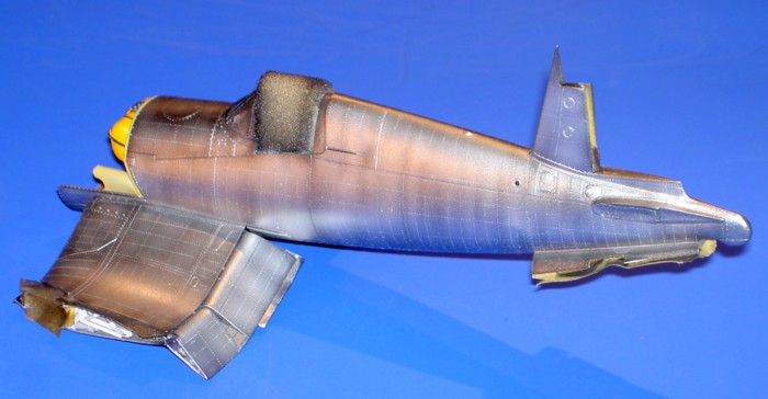
The evaluation of the available reverence material resulted in my
judgement that this range including all construction units as well as
the fuselage was to be painted in non-toned Zinck chromate. Since I
wanted to do only a thin glaze like on the original I first primed the
entire surface covering in shining black that followed by a thin layer
Alclad „white aluminum”. I sprayed up the Metal colour and the following
zinc chromate extremely time-consuming panel for panel, so that the
result could be affected . Finally the panel lines should be
recognizable without a washing. Since I really laid now chromate-yellow
on different coloured surfaces painted by me before , it was adjusted at
the beginning mentioned effect: Numerous different yellow tones were the
result!
The installation of the engine once again demanded my whole attention,
thereby the exhaust pipes had to fit to holes on the lower surface, cut
out for it. The cowling, against the Aires guidance had to be fastened
to the cylinders, so still before painting sixteen crescent-shaped
mounting plates was punched out and glued to the inside. Outside
appropriate rivets for it had to perforate.
As on the original photo recognizable, the outside wing areas, the
control surfaces of the height and vertical stabilizer and canopy which
were already pre-coated, and so I tried to reconstruct this proceeding
also at the model. I went without the metal priming, but did the yellow
protective coat. I sprayed all fabric surfaces grey. I mention here once
again that I so pedantically proceeded, because I had to represent an
exterior fresh from the factory and wanted to do without a washing!
For preshading on the top side of the wings I used the non-coloured and
pure colour, afterwards I easily lightened the panels. For the
structures of the rudders and fabric segments I lightened this clay/tone
again and afterwards then preshaded with it the engravings on the lower
surface and the horizontal tail. Also this intermediate blue was still
lightened twice. With the lower surface, stub wings and the center
section I began with light-grey semi gloss and brightened with shining
white to reach more depth also here. As a result of toning high gloss
„gloss sea blue” with semi gloss white arose a not too reflecting
finish, and also the semi gloss „Intermedia blue” offered still a
sufficiently smooth surface to apply the Decals perfectly, which I cut
out anyway sharply around. Since after a polish with „Micromesh” the
gloss level was almost identical I could save sealing.
Final Assembly
This involved bonding the control surfaces into angled positions,
fitting the landing gear parts including drawing in mechanisms and
draping the brake hoses from black painted cord. After inserting the
cannons and gluing the weapon pit- and ammunition-flaps to the outside,
the wing areas could be aligned finally perpendicularly standing and
were fixed after detailing the bolting device mechanics. I not simply
set on it but fastened the canopy in front and in the back with tiny
taps in the guide rails.
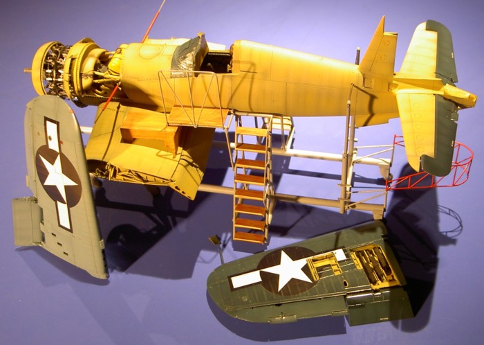
The engine compartment was still wired up with differently coloured
wires and where it appeared necessary and probable to me I still stuck
various maintenance plaques up.
After jacking up I provided one propeller blade with the label sketched
with “Window Word”: “Don´t rotate…”
Click the thumbnails below
to view larger images:
[../../photogallery/photo00004299/real.htm]
Model, Images and Text Copyright © 2007
by Hubert Ortinger
Page Created 04 October, 2007
Last Updated
24 December, 2007
Back to
HyperScale Main Page
|
 Home
| What's New |
Features |
Gallery |
Reviews |
Reference |
Forum |
Home
| What's New |
Features |
Gallery |
Reviews |
Reference |
Forum |