|
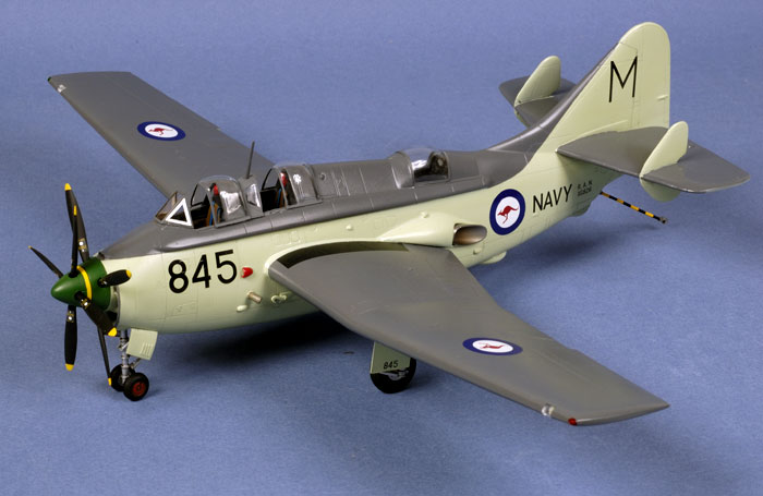
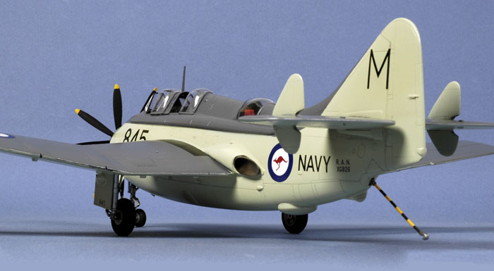
Classic Airframes' 1/48 scale
Fairey Gannet ASW
by Brett Green
|
 |
|
Fairey Gannet ASW |

Classic Airframes' 1/48 scale Fairey Gannet is available
online from Squadron
Background*
If ever there was a nation that was painfully aware of the effect of
submarine warfare, it was Great Britain. Near the end of the Second
World War, it was clearly recognized that a dedicated anti-submarine
warfare aircraft was needed, and the Fairey Firefly was not capable of fulfilling that role.
Specification GR. 175/45 was put out at the end of 1945 for a dedicated
anti-submarine warfare aircraft that was also able to perform anti-shipping
duties. Gr. 175/45 was also grounded in a technology that had been
previously developed by Fairey, that was the use of two engines, each with
its own crankshaft to power co-axially mounted, contra-rotating props.
This had great advantage for carrier based aircraft in that there was
the safety of two engines, rather than one; the engines could be mounted
in the fuselage, rather than enlarging the wings to accommodate two
propulsion units; and contra-rotating props eliminated the effect of
propeller torque. Another advantage of such an arrangement was that one
engine could be shut down to conserve fuel and extend flight time, an
important factor in long-range anti-submarine patrols. With the
improvements in turbo-engine design, the Armstrong Siddeley Mamba engine
became the power plant of choice. When Fairey coupled two together for
its proposed Type Q (the Gannet) it became know as the “Double Mamba”.
Development of the Type Q began in 1946, but it was not until 19 June
1950 that the first Type Q actually engaged in flight deck trials on HMS
Illustrious. On that date, the Type Q became the first turbo-prop
aircraft to takeoff and land on an aircraft carrier. Nearly another
three years would go by until the first production Gannet AS. 1 made it
debut in June 1953 and two more years until the gannet entered
operational unit service with 826 Squadron in January 1955.
The AS.1 Gannet had a crew of three - pilot, observer and rearward facing
radar operator. Its offensive weapons were carried in the weapons bay,
which could accommodate various combinations of torpedoes, depth
charges, sea mines, conventional high-explosive bombs and sonobouys.
Four mounting points under the center section of each wing could be used
for up to 24 unguided rockets.
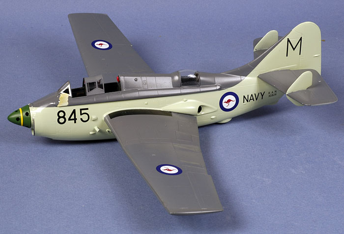
Classic Airframes' 1/48 scale Gannet in the box
The Fairey Gannet is right in the middle of Classic Airframes'
subject sweet spot - a 1950s Fleet Air Arm aircraft that has never
before appeared as a 1/48 scale injection moulded kit.
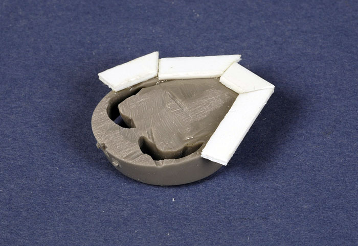
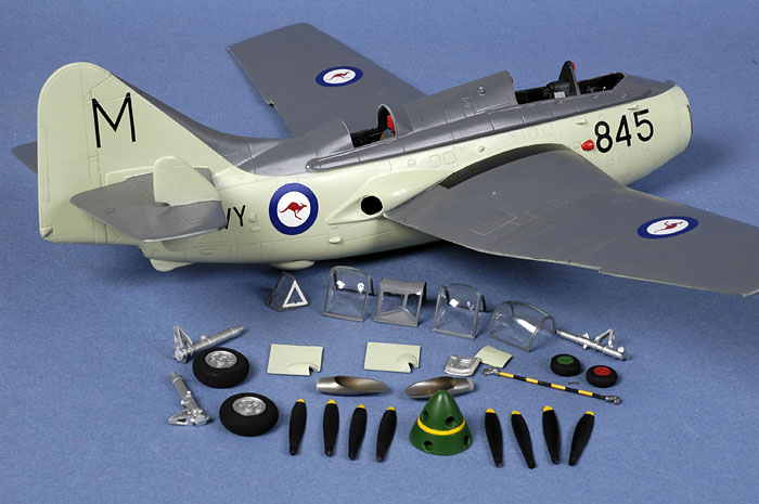
Classic Airframes Gannet comprises 56 parts in shiny grey plastic, 29
parts in grey resin and 7 clear injection molded parts. Markings for
British, Indonesian and Australian aircraft are included.
The quality of the plastic is very good, with no sink marks or
ejector pins in obvious locations. Being a limited run model, however,
there are no locating pins so test fitting and careful alignment will be
essential during construction.
The resin parts are beautifully detailed, convincingly fitting out
the three cockpits and wheel wells. The casting blocks on the wheel well
and nose parts are quite imposing, so a stout razor saw or a cutting
wheel attachment on a Dremel motor tool will be the order of the day.
Clear parts are free of distortion. Separate sections are supplied
for each of the canopy parts, so the modeller can choose which sections
to slide open and which to keep closed.
For a more detailed examination of the kit contents,
see Steven "Modeldad" Eisenman's review elsewhere on HyperScale.

If you have built one of Classic Airframes recent larger kits such as
the Anson or the Canberra, you will have a good idea of what to expect
with this new Gannet.
The most important step is careful and thorough preparation of the
kit parts prior to assembly, both plastic and resin. I spent around an
hour and a half removing flash from the kit parts and separating resin
pieces from their casting blocks.
For the large nose casting, I started by cutting a groove into the
back of the part using my trusty razor saw. This gave a definite line of
demarcation between the resin part and the casting block.
Once I had cut all the way around the nose part, I
attached the round cutting wheel to my Dremel Motor Tool. This was used
to "slice and dice" the rear of the casting block, all the time being
careful to avoid intruding on the part itself. The smaller blocks
resulting from the "dicing" were then ground off with the cutting wheel.
The Dremel was also used for the casting blocks on the
wheel wells, rear cockpit tub and the second cockpit's radar unit.
Test fitting the resin nose casting against the front of
the fuselage showed a mismatch - the diameter of the nose was slightly smaller than the
front of the fuselage. I corrected this by gluing plastic strip to the
back of the resin nose part as an extension plug. This was sanded back to match the contours
of the fuselage once the resin part is glued in place later in
construction.
Click
the thumbnails below to view larger images:
[../../photogallery/photo00022489/real.htm]
I was very pleased that the nicely detailed mail wheel
well parts fitted easily inside the wing halves without the need for any
further thinning. I did manage to accidentally cut through the top of
one of the wheel wells with my Dremel though!
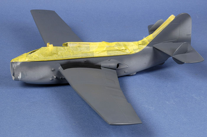
With the wings assembled, I test fitted them against the
fuselage (which was taped together and fitted with the supplied wing
spar).
The fit was not completely flush and the wing was wider than the wing
root, so I sanded the mating edge of the wing back with a coarse sanding
stick. The spar interfered with the fit too, so I sanded the top and
bottom on both sides. On the starboard side, the fuselage exhaust
fairing prevented the rear of the wing from fitting properly, so the
top-rear of the wing was sanded back as indicated by the hatching in the
photo below.
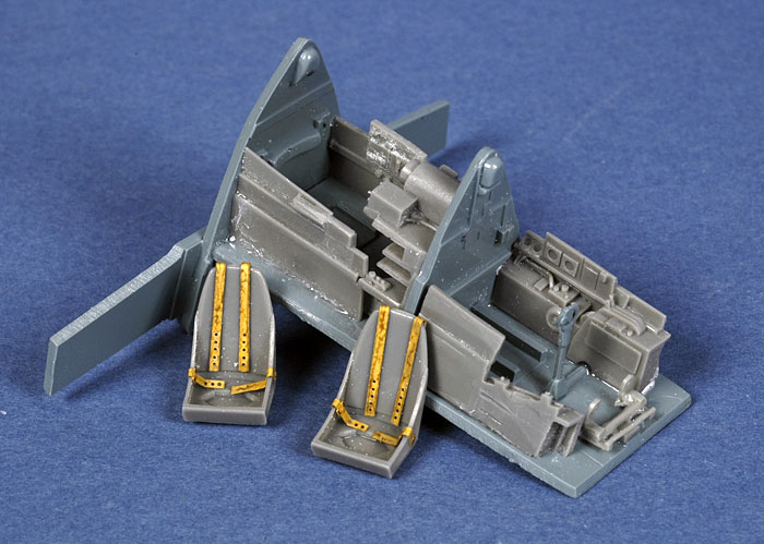
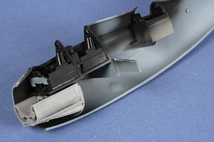
The cockpit parts were now assembled. The exact position
of the side consoles is a little vague, but I managed to get it right
the first time after test fitting. I found that all the cockpit
components fitted exactly as they should, and the very clever method of
mounting the cockpit on the wing spar worked perfectly.
The assembled cockpit was test-fitted to the fuselage to ensure precise
fit. The rear cockpit is simple, but looks fine.
The only after-market addition were Reheat photo-etched harnesses.
Click
the thumbnails below to view larger images:
[../../photogallery/photo00012169/real.htm]
The completed cockpits were painted using Tamiya NATO
Black - actually a very dark grey. Structural elements were highlighted
with a wash of thinned Lamp Black oil paint run along edges and in
shadow areas. Small details such as switches and handles were picked out
with a fine brush.
Of course, Murphy's Law struck after the cockpits were painted and
installed inside the fuselage.
Chris Hughes sent a bunch of very useful
photos clearly showing orangey-red bakelite seats and blue harness
straps! I later popped the seats out of the assembled model for repainting.
While still blissfully ignorant of my colour faux-pas, I glued the
cockpits and the nose wheel well to the starboard side of the fuselage.
The cockpit and wing spar fitted perfectly.
Note that I intentionally positioned the wheel well around 1.5mm further
forward than the locating mark on the port side of the fuselage. This
means that the front of the wheel well extends beyond the plastic
fuselage halves. This ensured that the ducting lined up with the
extended resin nose part.
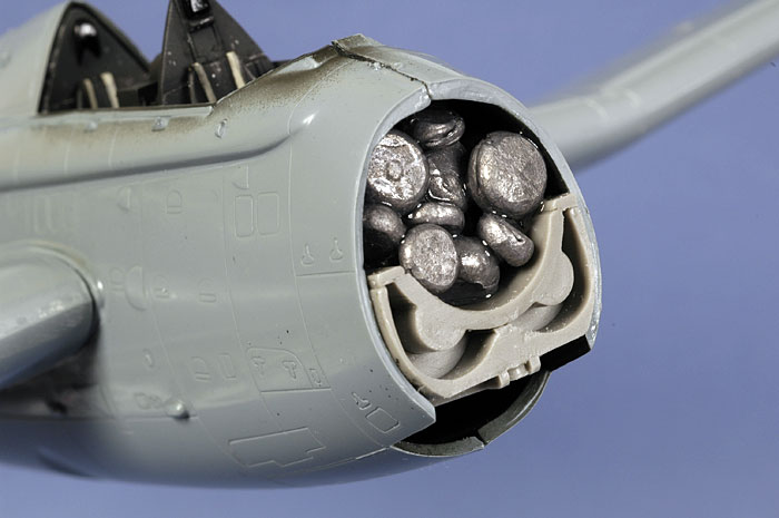
Classic Airframes' Gannet needs plenty of nose weight. Before buttoning
up the fuselage, I flattened some lead sinkers and glued them into the
cavity between the intake ducting and the bottom of the fuselage. More
weights were added when the fuselage halves are joined.
Click
the thumbnails below to view larger images:
[../../photogallery/photo00032462/real.htm]
The fuselage was now ready to be glued, taped and
clamped. I started at the rear, first gluing the tail halves, clamping
the parts, then using Tamiya Extra Thin Liquid Cement to secure the
bottom fuselage seam, the top mid fuselage and finally the upper nose
seam.
All these joins were taped until the fuselage had thoroughly set. Fit
was good once the parts had been clamped to eliminate any minor steps.
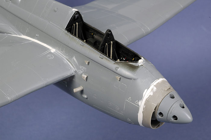
With the fuselage halves joined, it was time to add the
wings.
The wing roots had already been sanded with a coarse Mastercaster
sander, and the top and bottom of the wing spars trimmed slightly to
improve the fit.
The fit at the top of the wing was very good on both sides after these
tweaks.
The tailplanes were also attached. The large horizontal stablisers are
simply butted up against the empennage with no locating pins or tabs, so
I reinforced this important join by drilling holes in the tail plane
roots and through the tail to permit the installation of a brass
locating rod. There was a slight wedge-shaped gap at the front of the
tail plane roots, but this would be easily dealt with using Milliput a
little later on.
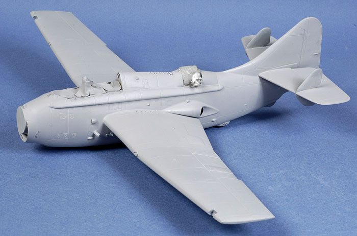
Now we have something that looks like a Gannet!
With both the wings and the tailplanes in place, I could figure out how
much additional nose weight would be required. I balanced the model with
my fingertips under the mounting points for the main undercarriage legs,
repeating this test as I progressively packed the nose with more lead
weights. With the nose cavity just about crammed full, there was finally
enough weight to tip the nose forward.
Click
the thumbnails below to view larger images:
[../../photogallery/photo00010676/real.htm]
Now the model was ready for installation of the nose,
plus filling and sanding.
The fit of the wing to the wing roots was less than perfect underneath.
The port side in particular left quite a deep trough between the
fuselage and the wing.
Fortunately, this was easy to fix by filling with
Milliput.
Milliput was also used to fair in the resin nose casting. I had earlier
built up the rear of this undersized resin part with plastic card to
match the contours of the plastic nose.
The forward propeller spinner very slightly overlapped
the rear section, and the rear section very slightly overlapped the
forward fuselage. The base of both parts were sanded back usig a coarse
Mastercaster sander.
A few very small gaps and steps were also filled with the same batch of
Milliput.
Milliput was used to fill the small gaps at the leading
edges of the stabilizer roots. A smear of Tamiya Surfacer was all that
was required to fair in the tailplane finlets. Note that the tall
finlets should be fitted to the top of the stabilizers - the
instructions are a little ambiguous about this. A tiny spot of Milliput
was also applied to the front of the winglets.
Painting,
Decals and Weathering
|
Primer and More Assembly
 A
second round of Milliput was applied before a coat of Tamiya Grey Primer
was sprayed over the model straight from the can. A
second round of Milliput was applied before a coat of Tamiya Grey Primer
was sprayed over the model straight from the can.
I find that this is an important step when building limited run kits in
particular, as it will help identify any persistent gaps or seam lines,
and panel lines lost during the filling and sanding stage.
All the imperfections were highlighted with a pen for later attention.
Click
the thumbnails below to view larger images:
[../../photogallery/photo00019406/real.htm]
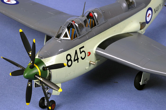
The spinner was painted prior to assembly. This made painting the yellow
stripe a little easier. The green shade is a 50/50 mix of Tamiya Park
Green and Gloss Green.
Before starting the paint job, I added lamps to the
landing lights. These were punched circles of plastic card, painted
silver and with tiny piece of white plastic rod glued to the centre to
represent the bulb. A blob of two-part epoxy cement (Araldtite) was
applied over the plastic circle, encasing the plastic light bulb. Once
the cement had dried, I brush-painted a coat of Future over the top. The
epoxy glue is nice and glossy, but the Future will protect the sheen
from frosting when it is superglued into the landing light recess.
Of course, it would be easier if I could just find a
local source for MV lenses!
Paint
All
paint was applied with my Testor Aztek A470 airbrush fitted with the
fine tan coloured tip.
Painting started with a coat of
Xtracrylics Ocean Grey (a bit paler than Extra Dark Sea Grey, so a nice
representation of a faded version of the upper surface colour). The
black wing walks were also masked and sprayed at this stage.
Next, the grey upper surfaces were
masked using various widths of Tamiya masking tape. With the large areas
of Sky on these Fleet Air Arm aircraft, I find it faster and easier to
adopt this "reverse masking" approach.
Alclad Magnesium was sprayed on the outer rim of the nose intake. A thin
strip was then masked with Tamiya tape.
Now, Xtracrylics Sky was now sprayed onto the remainder of the airframe.
Click the thumbnails below to view larger images:
[../../photogallery/photo00030284/real.htm]
When the masking tape was removed, the camouflage finish was revealed
in its stark, clean glory. Unfortunately, the tape had lifted a large
section of grey paint and primer from the starboard wing's leading edge,
and a smaller chunk from the top of the port wing.
I carefully sanded back this damage before masking and respraying
these sections. The operation was successful, but when I removed the
masking tape from the wing camouflage demarcation, it lifted a new chunk
of Sky paint and primer!
So it was back the the masking tape again, but this time I reduced
its tackiness by applying it to my forehead and removing it. My
specialized anti-tack head did the job, and no further paint was
damaged.
Decals
The model received a coat of Polly
Scale Gloss acrylic before the markings were applied. I find that the
Polly Scale clear finish can be more easily controlled than Future when
spraying, does not run on horizontal surfaces, yet still delivers a
hard, shiny finish ideal for decals.
I used the Classic Airframes kit
decals, which are very thin and settled down beautifully into panel
lines.
The completed paintwork was sealed
with a a further coat of Polly Scale Gloss acrylic.
Finishing Touches
All the smaller detail parts were
cleaned up and painted.
Because I had moved the nose casting
forward, the opening for the front gear bay was slightly longer. I
therefore had a choice of filling part of the gear bay or extending the
length of the nose gear doors. I chose the latter. A small piece of
plastic card was glued to the front edge of each nose gear door, faired
in with Milliput and sanded smooth when dry.
I particularly enjoyed the painting of
the nose wheel hubs - red for port and green for starboard. As it must
have been pretty obvious what side of the aircraft was port and
starboard, I can only assume that the nose wheel assembly was capable of
free castoring, and the colours warned the ground crew if the wheels
were rotated 180º. If someone has a better
explanation I would be interested to hear it.
Classic Airframes' clear parts are well presented, but the canopy centre
section and two sliding canopies are slightly too short. This could be
addressed by adding strips on plastic to the bottom edges of the parts,
but I decided to use the spare vacform canopies from Dynavector's 1/48
scale Gannet. These fitted very well.
The injection moulded windscreen and rear cockpit canopy from the
Classic Airframes kit were used, as these both fitted perfectly. White
decal film was cut into fine strips and used to depict the white sealing
tape sometimes seen on Gannet windscreens. With the benefit of
hindsight, however, these are far too wide.
The distinctively striped tail hook was masked and sprayed yellow and
black.
The resin jet exhausts were first painted Alclad Magnesium, then
"scorched" with a thin mix of Tamiya Flat Black and Red Brown, applied
more heavily to the
The undercarriage legs mated positively with their locating holes in the
wheel wells. However, the main gear legs have a slight (and accurate)
forward rake. This shifts the centre of gravity slightly forward,
meaning that the nose weight was now insufficient to keep the nose wheel
on the ground. Fortunately, there was enough space inside the forward
wheel well to stuff another six squashed lead fishing sinkers, and the
nose wheel now gently kisses the tarmac - but only just!
Weathering
This was one of the most challenging weathering jobs I
have ever done. I had a great deal of difficulty restraining myself from
adding at least a modicum of grime to the airframe. However, these Royal
Australian Navy Gannets were kept quite clean, so I resisted the
temptation.
The only weathering was an extremely thin wash along
panel lines on the nose and beneath the empennage, and a slightly
heavier wash in the rudder hinge line. I did not even dirty up the tyres.
Apart from that, I added an oil wash to the
undercarriage legs and the wheels.
Wing tip lenses were depicted using Tamiya Clear Red and
Clear Green.
It is great to finally have an injection moulded Gannet in 1/48
scale.
In common with most recent Classic Airframes kits, after careful
preparation and regular test fitting this model delivers a
great looking and well detailed result with nicely restrained surface
texture.
As pointed out in the article text, the main issues to watch out for
are fairing in the undersized resin nose casting and making sure that
the cockpit parts are precisely aligned. Some filling underneath the
wing roots will be necessary too.
However, none of these challenges are
beyond the capabilities of a moderately experienced modeller. I would
rate the degree of difficulty as similar to the Classic Airframes
Dornier Do 17 Z.
Thanks to Classic Airframes for the
sample.
Photography
The model was photographed in
HyperScale's studio using a Nikon D70 digital SLR. Illumination was via
two studio flash units - one Bowens 250 and a generic 100 flash - on
stands and illuminating from a high 45º angle from each side of the
front of the photography table.
The camera was fitted with a Micro
Nikkor 60mm lens.
ISO was set to 250, and the manual
shooting settings were 1/100 of a second at f.29. The high aperture
ensures good depth of field.
Model,
Images & Text Copyright © 2007 by
Brett Green
* Background Text Copyright © 2007 by Steven "Modeldad"
Eisenman
Page Created 12 September, 2007
Last Updated
24 December, 2007
Back to
HyperScale Main Page |
 Home
| What's New |
Features |
Gallery |
Reviews |
Reference |
Forum |
Home
| What's New |
Features |
Gallery |
Reviews |
Reference |
Forum |