|
Model Design Construction's 1/32 scale
Hawker Typhoon Mk.Ib
by
Ian Robertson
|
|
|
Hawker Typhoon Mk.Ib |

HyperScale is proudly supported by
Squadron.com
 The
Hawker Typhoon was intended as a replacement for the Hurricane in the
interceptor role for the British. When it was introduced in 1941 it
was the only Allied fighter capable of speeds higher than the Fw.190 at
low altitudes. However, the Typhoon was plagued by early design flaws
and never reached its full potential as a fighter for so long that it
was no longer needed in that role. The
Hawker Typhoon was intended as a replacement for the Hurricane in the
interceptor role for the British. When it was introduced in 1941 it
was the only Allied fighter capable of speeds higher than the Fw.190 at
low altitudes. However, the Typhoon was plagued by early design flaws
and never reached its full potential as a fighter for so long that it
was no longer needed in that role.
Following several design upgrades, the Typhoon’s
real forte as a hard-hitting ground attack aircraft was eventually
recognized and used to advantage by the Allies. Fitted with either
rockets or bombs, the Typhoon proved very effective against ground
targets throughout occupied Europe.
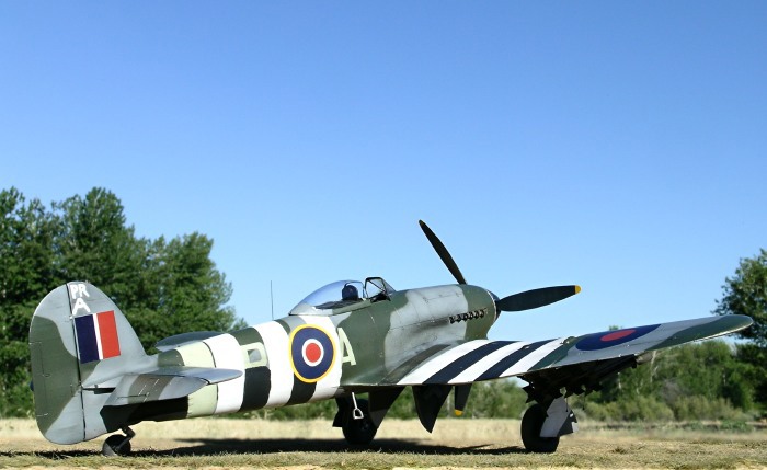
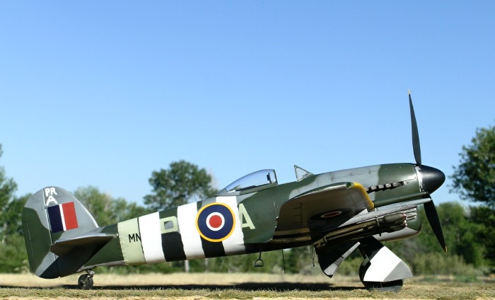
My model represents a rocket-laden Typhoon Mk.1B
poised to strike German targets in France on D-day. This particular
aircraft belonged to No. 609 Squadron flying from Thorney Island in the
UK (see photo on pg 16 of Warpaint #5). Like many early rocket carrying
Typhoons, this aircraft had a three bladed propeller.
MDC’s 1/32 scale Typhoon Kit
In 2005, MDC released its first complete model kit
in the form of a resin 1/32 scale Typhoon Mk.1B with teardrop canopy,
tempest tailplane, and optional spinner/propellers (3 or 4 blade).
Since that time MDC has released a resin 1/32 Ki-61 Tony, and is set to
release a resin 1/32 Arado Ar.234.
The MDC Typhoon kit features numerous subassemblies
molded in light grey resin with finely engraved panel lines. The kit
also contains metal landing struts, a vacuform canopy, and decals for
several schemes. The detailing on the resin parts is superb, and the
fit is like what one expects from a mainstream injection-molded kit.
The fact that this kit is resin should not deter modelers interested in
building a large scale Typhoon. However, it is not cheap and some
building experience is required. The instructions are a let-down
because they are vague and difficult to read. I ended up downloading
images taken by those who built the kit before me in order to make sense
of the finer details of assembly, particularly for the cockpit.
However, the main aspects of assembly are obvious and straight forward
to someone familiar with building aircraft models.
Cockpit
Construction begins with the cockpit…..I found this
out when I sat down to start the kit and realized that the cockpit was
missing from my kit! My email to MDC was answered in very short order
and a replacement cockpit was sent to me at no charge within days
(thanks Bob!). Excellent customer service by MDC, particularly given
that a year and a half had passed since I purchased the kit.
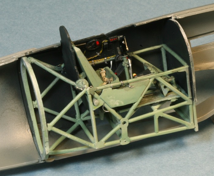
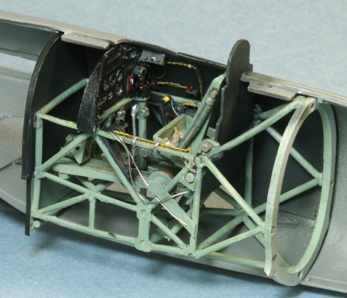
The cockpit consists of several panels of tubular
framework, a floor panel, seat, control stick, rudder pedals, and
bulkheads. A minimum amount of cleanup was required for the parts. I
added some wiring and switches etc for the upper cockpit sidewalls since
these were bare in the kit.
I opted to paint the tubular framework RAF interior
green, and the sidewalls, armor plate and headrest black. Some
references suggest the entire cockpit should be black, whereas others
suggest the tubular framework should be natural metal.
In any case, there’s not much to see of the cockpit
once the fuselage halves are glued together.
Fuselage
Before gluing the fuselage halves together, be sure
to add the exhausts and radiator details.
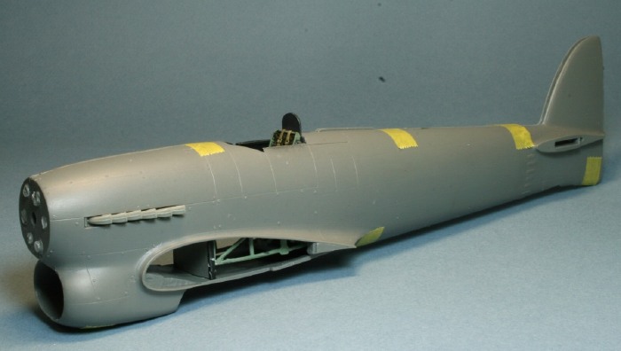
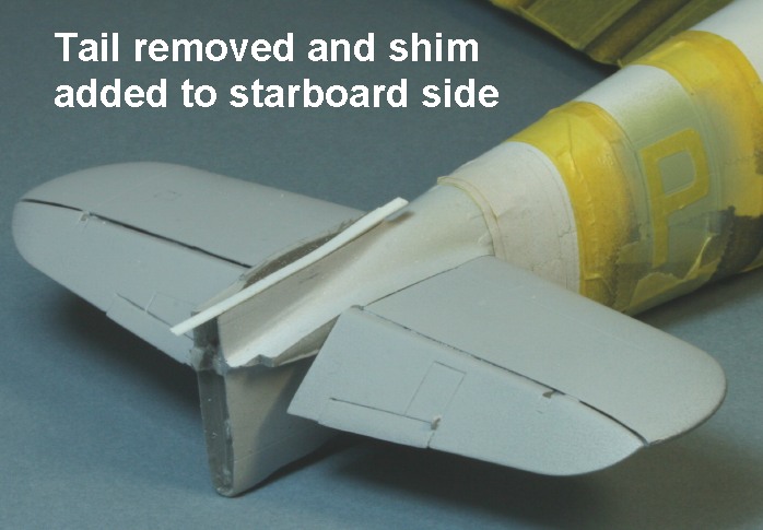
Although gluing the fuselage halves together
presented no (apparent) difficulty, several days later I noticed that
the tail leaned starboard, throwing the model’s alignment completely out
of whack. This error may have been a consequence of misalignment when I
glued the fuselage halves together (i.e., my fault), or perhaps the
parts were warped from the outset (i.e., not my fault). In any case,
the real question was how to fix the problem. I decided to remove the
tail (above the horizontal stabilizers) and add a styrene shim on the
starboard side to straighten the tail out. The tail was then reattached
with CA glue, and the seam was carefully filled and sanded smooth. It
may seem like major surgery, but the entire process took about 20
minutes and made a huge difference to the look of the model.
Click on the thumbnails
below to view larger images:
[../../photogallery/photo00014929/real.htm]
Undercarriage
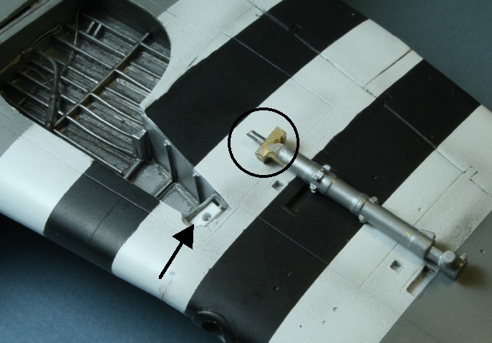
When dry-fitting the struts and wheels I got the
distinct impression that the model would sit low at the nose if I
positioned the struts at their proper forward rake. Indeed, the model
sat 8 scale feet at the tip of the spinner (on unweighted tires), but
drawings in the Warpaint book (modified from originals by A.L. Bentley)
indicated that the aircraft should sit about 9 feet high. To fix this
problem I added a small piece of styrene to the rectangular well that
holds each strut (see arrow in photograph). These pieces of styrene
extended the struts enough to raise the nose to its proper height. I
added a metal pin to each strut (see circle) to give the strut greater
stability when plugged into the well. I then used 5 minute epoxy to
glue the struts in place. The extended setting time of the glue gave me
time to ensure the struts were properly positioned.
I set the rake of the undercarriage using the
drawings in the Warpaint book as a guide. According to the drawings
(and photos), the rear part of the gear door’s lower edge should be
more-or-less horizontal with the ground. In many models this part
slants upward to the rear, indicating that the struts are not raked
forward enough.
Also, with proper rake, the center of the wheel hub
should align vertically with the rear of the second exhaust stack.
Wings
MDC provides separate wing flaps with lots of
internal detail – ideal for displaying the flaps in their dropped
position. However, I couldn’t find any photographs showing a parked
Typhoon with its flaps dropped, so I opted to leave mine raised. In
doing so there were some large gaps to fill with strip styrene and putty
along the edge of the flap where it meets the wing. My guess is that
the flaps were designed to be displayed down, not up.
The wheel wells are well detailed and the wings fit
solidly into the fuselage. I faired over the light on the leading edge
of each wing, something that most modelers miss when building a rocket
carrying Typhoon. According to Thomas (Warpaint #5, pg 25), and backed
up by photos, the wing lights on rocket-carrying Typhoons were faired
over because of fear that the Perspex would catch fire from the
rockets. Some later Typhoons apparently had a single wing light. Check
your references.
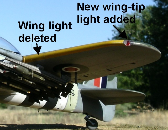
Although MDC supplies clear resin for the wingtip
lights, I opted to make my own from clear sprue. A hole was drilled in
the back of each wingtip light so that I could add a drop of Tamiya
clear red (port light) or green (starboard light).
Canopy
I was not impressed by the canopy that comes with
the kit (the framing was soft and vague) so I replaced it with one from
Squadron. Kent Eckhart provided the canopy I used – Thanks Kent, I hope
I can find you a replacement!
Rockets and Rails
MDC does not supply the rocket assembly with their
kit, so you will have to order it as a separate item. Some of the rails
in the set I purchased (item CV32023 - high explosive rockets) were
warped, but I corrected the problem by placing the rails in near-boiling
water and straightening them out. I used fishing line with a dollop of
white glue on the end to simulate the electrical firing leads.
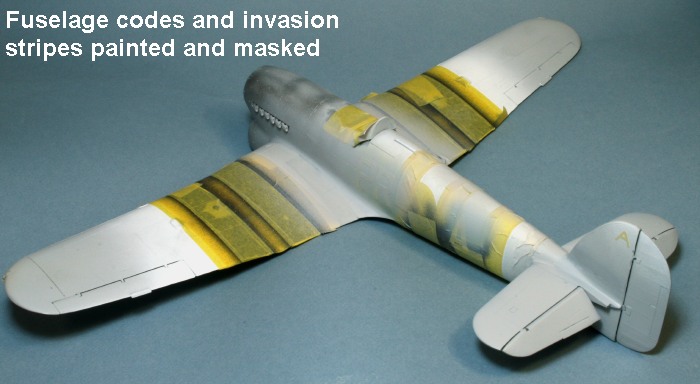
I painted and masked the fuselage tail band and
codes using Tamiya RAF Sky (XF-21). I then painted and masked the
invasion stripes using Tamiya White primer and Polly Scale black (with
some grey added). Note that the invasion stripes on this aircraft had
rough edges, and that the black stripes did not extend over the upper
half of the fuselage.
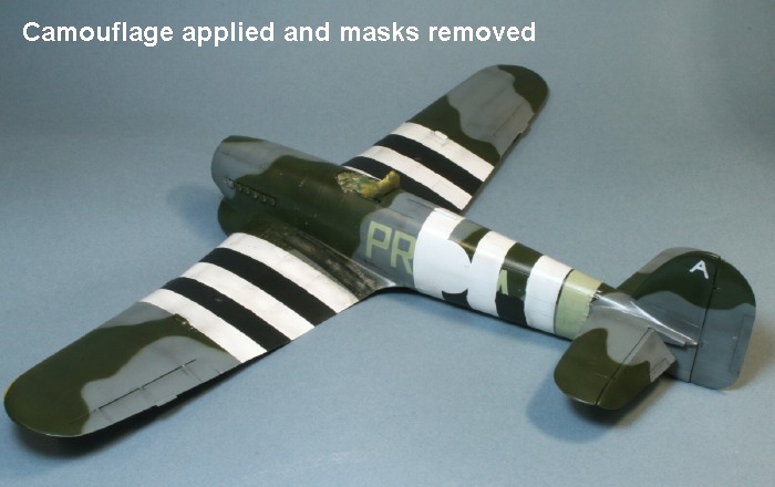
I painted the camouflage with Xtracrylix RAF Ocean
Grey and Dark Green over Medium Sea Grey. Although not shown in the
photo, the rear decking beneath the canopy was eventually painted
black. The wheel wells were painted with Alclad II duraluminum. The
spinner was first painted duraluminum and then scale black. I lightly
sanded the rear edges of the spinner to expose some of the aluminum.
The serial number for this aircraft is known only
as far as the MNxxx block. I mixed and matched numbers from the MDC
decal sheet to create MNx30. My decals for the fuselage roundels were
slightly out of register so I used spares from an Aeromaster sheet.
Exhaust stains were airbrushed on using highly
thinned black Polly Scale acrylic.
A wooden cutting board was used as the base for the
model. Celluclay was used to make the basic ground cover. The
celluclay powder was mixed into a paste with water and white glue,
tinted with brown acrylic paint, and then spread thinly over the cutting
board. Note that the cutting board had previously been treated with
several coats of clear lacquer to prevent warping while the celluclay
dried. While the celluclay was still wet I added pieces of Heki grass
mat (item # 1574 - Wild Grass Savanna) and fine sand. Heki products are
available for purchase in the United States from “Scenic Express”.
Outdoor images were taken with a Nikon Coolpix 5400
digital camera. The “unsharp mask” tool of Adobe Photoshop was used to
restore some of the clarity and crispness lost during image
compression. The “blur” tool was used to help merge the base with the
natural background. Indoor construction shots were taken using a tripod
with a Canon EOS 30D fitted with a macro lens.
-
Scutts, J. 1990.
Typhoon/Tempest In Action. Squadron/Signal Publications.
-
Shores, C. & C.
Thomas. 2004. 2nd Tactical Air Force, Volume 1:
Spartan to Normandy. Classic Publications.
-
Thomas, C.
Warpaint Series #5: Hawker Typhoon. Hall Park Books.
Click on the thumbnails
below to view larger images:
[../../photogallery/photo00011839/real.htm]
Model, Images and
Text Copyright © 2007 by Ian Robertson
Page Created 21 September, 2007
Last Updated 24 December, 2007
Back to HyperScale
Main Page
|
 Home
| What's New |
Features |
Gallery |
Reviews |
Reference |
Forum |
Home
| What's New |
Features |
Gallery |
Reviews |
Reference |
Forum |