|
Trumpeter's 1/24 scale P-51D
A Big Aussie Mustang
by Mike Prince
|
North American P-51D Mustang
77 Sqn. RAAF |

Trumpeter's 1/32 scale P-51D Mustang is available online from Squadron.com
Background
In 1950 77 Squadron RAAF was ready to return to Australia, having spent four years operating in Japan as part of the occupation forces. Indeed, when the Korean War started on 25 June, the squadron was being run down and had flown what was thought to be its last sortie two days earlier.
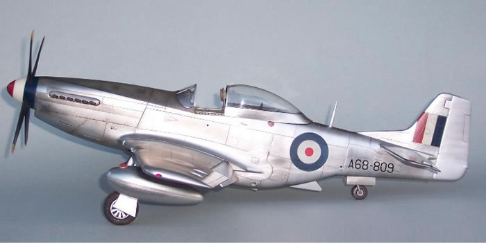
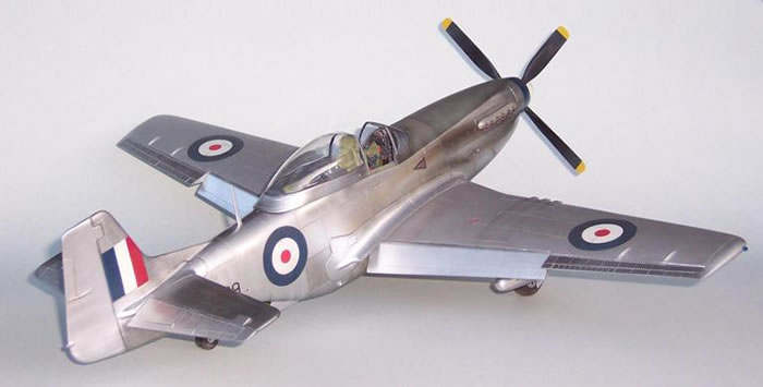
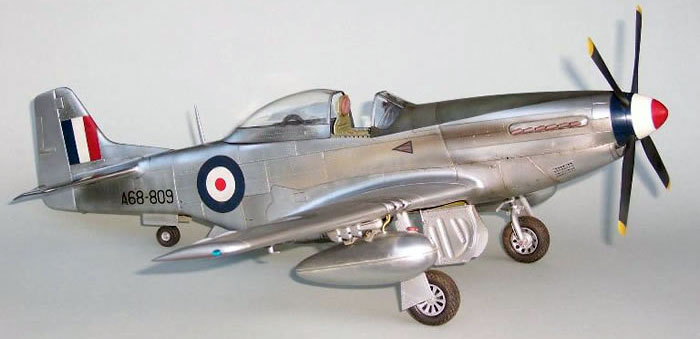
At that time, 77 Squadron was led by Squadron Leader Lou Spence and operated a mix of US built P-51D and P-51K Mustangs. These aircraft equipped the squadron until replaced by Gloster Meteors in April 1951 and were used in the highly dangerous role of ground attack. It was in this role that SQN LDR Spence met his death when his aircraft was hit by ground fire on 3 September 1950. It was his aircraft that I chose to model.
Trumpeter's Kit
Like many kits, the Trumpeter 1/24 scale P-51D has received its share of criticism. These have included comments regarding the nose, the level of interior detail and even the position of the cockpit. However, in my personal opinion, most of this is either unfounded or easily remedied. The shape of the kit is excellent with finely recessed detail – it runs rings around the older Airfix offering I built several years ago. As such, it proved a great basis for a model intended to showcase a weathered natural metal finish and a well detailed cockpit. While a blow by blow description of building this kit isn’t necessary, it’s worth pointing out a few tips and corrections identified along the way.
Cockpit
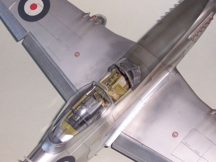
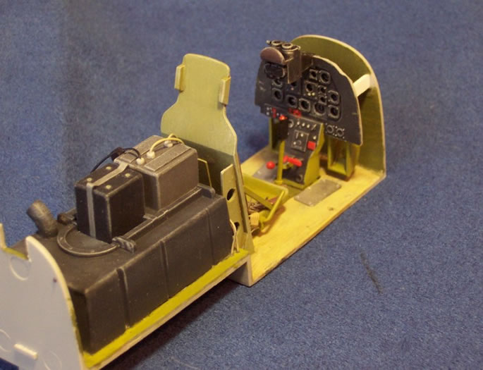
In this scale and with such a large canopy, the cockpit is a focal point and is worth a little extra effort. Out of the box it actually has quite a good level of equipment detail but is let down by the impression that it still looks too empty. This is mainly due to the lack of sidewall depth with the equipment looking tacked onto an otherwise flat sidewall, rather than nestled between frames and longerons. The seat also needs to be wider.
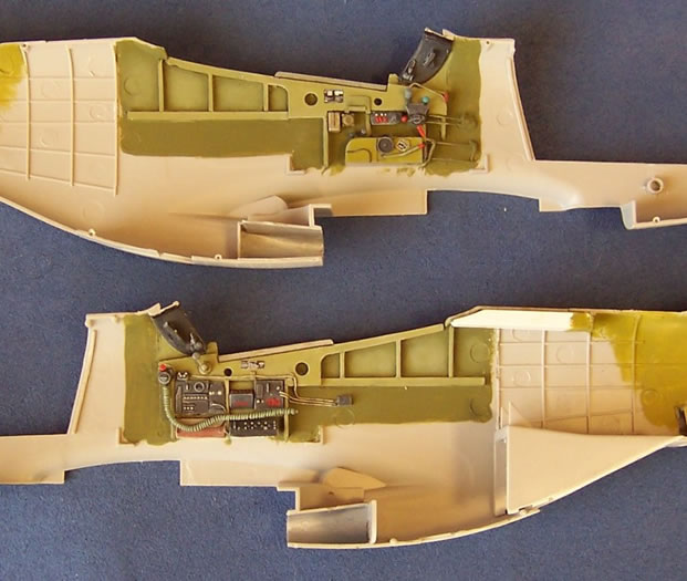
To remedy this, the structure of the sidewalls was beefed up significantly. This was done by adding internal framing using several layers of sheet plastic around the cockpit coaming and part-way down the sidewalls.
The accompanying photo shows this better than any written explanation. This was built up in layers and tapers in thickness from 2.5mm beneath the windscreen to 1.5mm just behind the seat. The inner-most layer included the canopy runners, which are prominent on the real aircraft but are absent from the kit. While tapering the sidewalls might seem a little odd, it actually results in canopy runners that are parallel, as otherwise, the fuselage opening tapers as the canopy sill rises from front to rear.
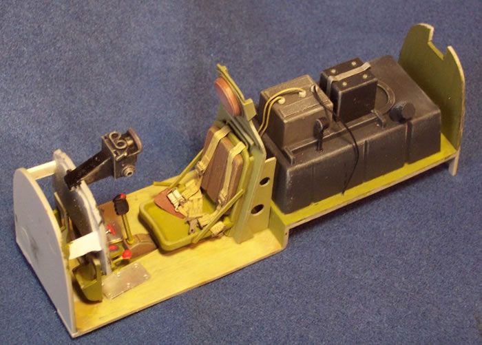
Ribs were then added running vertically between the various items of equipment and behind the seat. Kit equipment on the starboard sidewall was built up in thickness to match the new sidewall, while equipment on the port sidewall was a mixture of kit parts, a scratch built throttle quadrant and a new arm rest. The kit instrument panel was used along with the acetate instruments, while wiring was added using fine fuse wire.
Levers and controls were made from fine steel pins with a blob of white glue to form a knob on the end. To enlarge the seat, the pan was widened by cutting and adding a 2mm insert. A new seat back and cushion were made from sheet plastic, while the belts came from Eduard. The prominent hole in the back of the headrest was filled. The scuff plates below the rudder pedals were cut from thick aluminium foil, while the various placards came from the kit.
Aussie Mustangs of this era did not have an HF aerial exiting through the canopy so the guide was removed then the canopy polished and put aside for later. Other details included seat frames, auxiliary fuel tank filler pipe and associated fuel gauge, and boxing in the canopy runner on the fuselage spine.
Fuselage
Next, the fuselage halves were joined, remembering of course to include the radiator and rudder. I took great care here as any seam line was going to be highly visible under the NMF. All fuselage seams therefore had their edges chamfered prior to joining, with CA glue then run into the resulting ‘V’. As long as this is filed and sanded smooth within an hour or so of drying, the CA provides a flawless join every time. Additionally, unlike some other fillers, it doesn’t shrink over time.
While mention has been made in some circles that the cockpit is 3mm too far back this is not the case, it’s just that the kit would have you position the canopy open too far, thus appearing to shorten the aft fuselage. Solution; don’t open it quite so much. The front of the canopy should be about level with the pilot’s armour plate when open, not well behind it. I ignored the shape of the ‘warbird’ style blown canopy and left it as is.
Wings
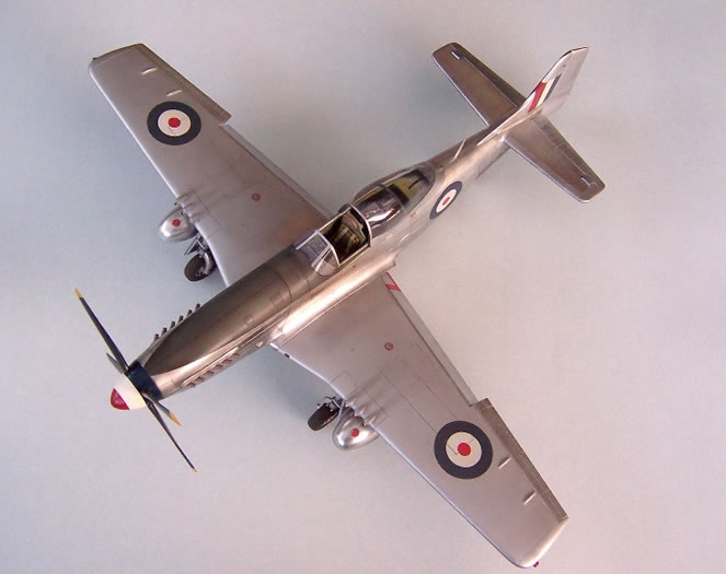
The wings are straightforward, though adding wing spars outboard of the gun bays proved necessary as they initially took on a ‘sucked in’ appearance without them. The detail in the gun bays is excellent, and will look great for those wishing to leave the gun bays open. However, the gun blast tubes are a little crude so were replaced with brass tube, while the fairings around them were considerably reduced in size. Remember that the inboard gun does not protrude out of the blast tube. The panel lines and rivets were filled with Tamiya putty as the wings on Mustangs were filled and doped, though I left a small strip along the wing roots with the detail showing so I could weather this walkway area later.
All control surfaces are designed to move, though installing the hinges and pivots involves finesse I just don’t have. After succeeding with the rudder I didn’t bother with the rest and simply glued them in place. The flaps required a little work to make them fit closely in the lowered position; this involved filing a flat on the leading edge of the flap and the corresponding lower trailing edge of the wing.
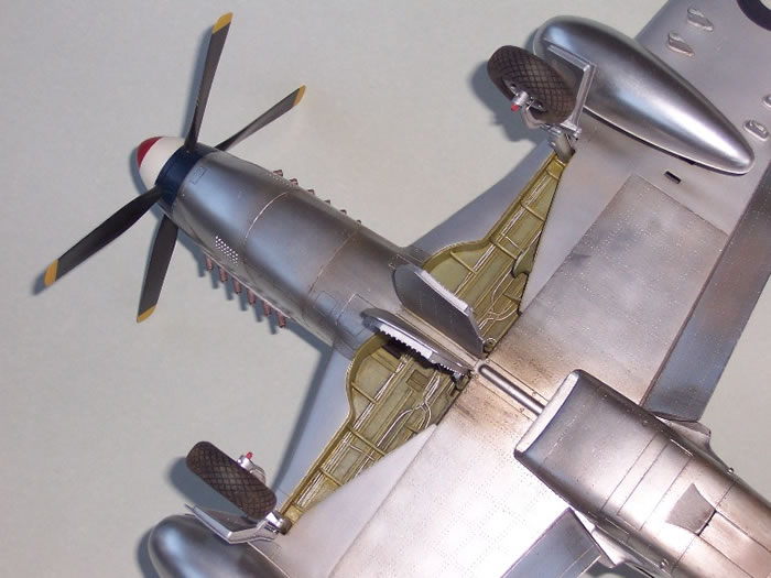
The wheel wells of Mustangs actually extended back to the main spar along their full length, but this is a feature I have yet to see depicted correctly on any Mustang kit. So, for the purist, the wheel wells could be modified accordingly. However, once built, the focal point of almost any kit is what can be seen when sitting right way up, so I chose to leave them as is and take advantage of the moulded in detail instead. This responded well to painting, a dirty wash and dry brushing.
In contrast, the undercarriage deserves a little work to improve the ‘sit’ of the model when finished. The undercarriage legs are designed to be sprung, with the lower part of each leg extending into the upper section and compressing a small spring. However, the weight of the kit is insufficient to compress the springs, leaving a very long legged appearance. The simple solution is to leave these springs out, though I actually went one step further and replaced the compression struts with brass rod to improve the strength of the legs. The vinyl brake lines in the kit were replaced with thick fuse wire.
Engine
While it has potential, the engine in the Trumpeter kit is too small; this is the only area where the Airfix kit can be considered better than the Trumpeter offering. I therefore left it out completely and replaced the propeller shaft with brass rod running from the firewall through a new bulkhead behind the spinner. The exhaust stubs were replaced with short lengths of aluminium tube.
Cowlings
If built out of the box the nose of the Trumpeter Mustang looks somehow odd. This is actually very easy to correct as the basic shape is excellent; it’s the misplaced panel lines on the sides of the upper cowling parts that make it look like the engine is angled upward.
These panel lines should actually run parallel to the lowest horizontal panel line, the one where the cowling parts meet the fuselage. This can be easily achieved by filling most of the existing lines and re-scribing them, using their positions behind the spinner as a starting point. The exhaust openings were also realigned by adding a small wedge and backing along the lower edge of the opening, then using the exhaust fairing as a template to file out a similar wedge along the upper edge. As there are actually two sets of cowlings in the kit (normal and clear) there’s very little risk of a terminal mistake here. After scribing, I replaced the lost fasteners by using the sharpened end of a steel tube from an old glue bottle in a pin vice.
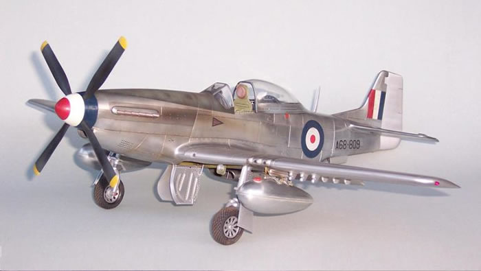
This was my first attempt at a natural metal finish and took three goes to get it right. I used Alclad II Airframe Aluminium on the fuselage, tailplane, flaps and ailerons. However, I initially had no end of trouble as the Alclad black undercoat seemed to stay soft and would not fully cure.
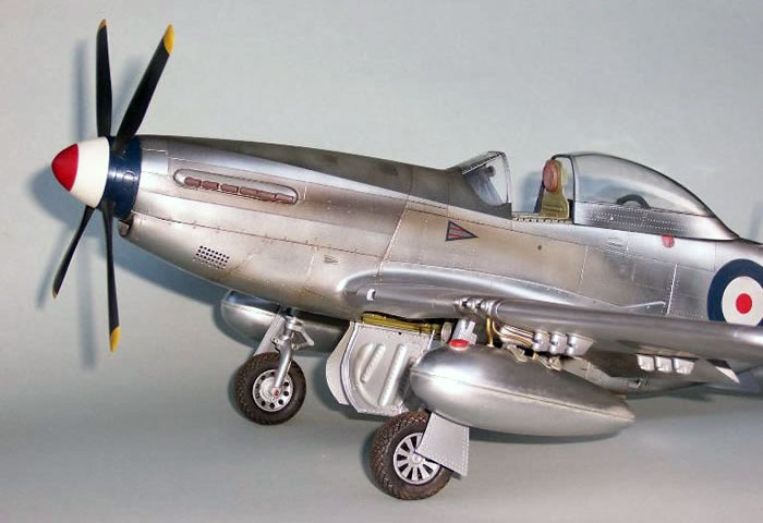
After eventually removing it all, I followed a friend’s advice and replaced the Alclad undercoat with a thin coat of Tamiya acrylic black followed by two thinned coats of Future. Using this system, the black undercoat highlights any scratches, while the gloss finish of the Future provides the foundation for a smooth metal finish.
When the Alclad II went over this combination I then had a smooth shiny finish that could be both handled and masked. When it later came to painting the drop tanks, I actually used only Future as an undercoat and, if anything, this actually worked better. Variations in panel tones were achieved using Alclad II Stainless Steel either lightly over-sprayed or mixed in various proportions with the Airframe Aluminium.
 In contrast, the wings and rudder were sprayed with Model Master non-buffing Aluminium to replicate the doped wings of uncamouflaged Mustangs. Panel lines were drawn in using a very sharp HB pencil, with gun smoke stains done using graphite powder from the same pencil, applied with a soft brush. Exhaust stains were applied by airbrush using a very thin mix of Tamiya Smoke and brown. In contrast, the wings and rudder were sprayed with Model Master non-buffing Aluminium to replicate the doped wings of uncamouflaged Mustangs. Panel lines were drawn in using a very sharp HB pencil, with gun smoke stains done using graphite powder from the same pencil, applied with a soft brush. Exhaust stains were applied by airbrush using a very thin mix of Tamiya Smoke and brown.
Markings came from Aussie Decals who do a great sheet for Aussie Mustangs in both 1/24th and smaller scales. The film conformed very well to surface detail, though I found that some of their printed colours became a little fragile when over-sprayed with Humbrol matt finish. However, after touching up and being protected with a brushed coat of Future, they perform perfectly well under a second coat of the matt finish, this time mixed with a drop of light brown to dull the markings and doped areas. Once dry, the matt finish on the wings was then scrubbed with fine steel wool in the walkway areas to create areas worn away by foot traffic, while the remainder was buffed with a soft cloth. Finally, the vinyl tires were sanded to remove the shiny plastic appearance before being slipped over the wheels, then the undercarriage, doors and other breakables attached.
In my opinion, Trumpeter did a great job with this kit. While the kit has a few minor detail errors these proved easy to fix, with the resulting model having a presence that just can’t be matched in smaller scales. If you like Mustangs, and particularly if you want one where the detail is large enough to be appreciated, one of these really should be on the to-do list. After all, while it might be a large scale, the model is still comparable in size to many 1/72 scale bombers, and for some, this may be just the ticket if all those tiny details are getting just a bit too small to see.
Model,
Text Copyright © 2008 by Mike Prince
Page Created 1 January, 2009
Last Updated 1 January, 2009
Back to HyperScale
Main Page |
 Home
| What's New |
Features |
Gallery |
Reviews |
Reference |
Forum |
Search
Home
| What's New |
Features |
Gallery |
Reviews |
Reference |
Forum |
Search