A Modeller's Guide to Italeri's 1/32 scale
Macchi C.202
Italeri Kit No. IT2518
by Maurizio Di Terlizzi
|
Italeri 1/32 Macchi C.202
Kit No. IT2518
|

Just in time for the 100th anniversary of the Italian Air Force, the Italian model company Italeri, released the long awaited Macchi C.202 in 1/32 scale. Before this kit, there were different models available on the market but almost all these kits are now sold out or not available.
More than a review, I would like that this article would be considered a sort of guide in the assembly of the Macchi C. 202, as a huge fan of this aircraft I started noting many issues that should be revised, eliminated or replaced to get a correct Folgore and I don't want that the less skilled modellers could build it with the most notable defects, continuing to perpetuate wrong information and common mistakes.
Plastic Sprues and Assembly Instructions |
First of all we checked the general dimensions that are correct both for the wingspan and for fuselage length without spinner. Plastic seems a little soft but the panel lines are printed good enough without sinkmarks. The biggest complaint is tied to the missing rivet lines, for a model kit issued in 2023 and considering the high recommended price and seeing what the other modeling companies are doing in smaller scale models, in my opinion the general rivet lines should've been done. Modellers could have chosen if to emphasize these rivet lines with a dark wash or to tone down their appearance, in any case they would've enhanced the realism of the model and put it more in line with the standard of the current modelling market.
These are the worst parts of the model kit, I am referring to the ailerons, rudder and tailplanes. Their plastic has raised details that should reproduce the effect of the fabric covering but unfortunately all these details are not to scale and unrealistic.
Ailerons
-
The canvas sags between one rib and the other and this is not good because in reality, it was very tensioned because of the tens of dope varnish, a couple of hands of Alluminata (it was a mix of alluminium powder and acetone and was used to avoid damage by the UV rays) and the camouflaged paint. The surface had to be very tight specifically to avoid flexing during the flight under the effects of kilograms of air pressure.
-
The raised lines seen on the surface should reproduce the protection tissue and the stitches that were done under the tissue across the ribs. The real pinked tissue stripes are 0.25 mm thick and after the many hands of glue, these details were rarely visible. The same thing can also be said for the stitching knots, reproduced as large semispherical raised rivets. Not to be pedantic, it must be said that Macchi’s control surfaces were stitched with a different method compared to other air forces, using a double parallel sewing pattern that resulted in a completely different appearance; even if the Italeri’s control surface details were acceptable with a single knot in the middle of the ribs, they were wrong anyway.
-
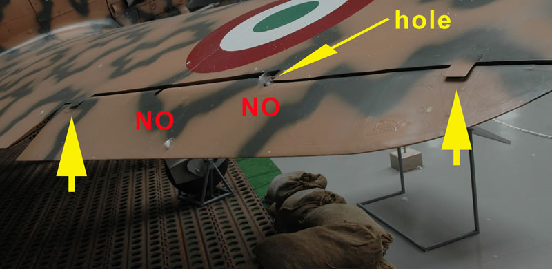
The ailerons were attached to the wings with 4 hinges, the 4th starting from the wingtip had a small oblong hatch to allow access to the aileron dissassembly bolt, while the second was “exposed” to be lubricated. Instructions tell modellers to cover the 4 hinges with small rectangular photoetched covers, but it is a mistake because on both the upper and lower wing surfaces, we have to cover only hinges number 1 and 4.On the step between wing-aileron, we have to do a 0,4 mm hole in the inner corner, used to dissassemble a fitting bolt
Tailplanes
Here, we have the same issues of the ailerons, they too have completely unacceptable surface details but the biggest mistake is that movable tailplanes were built with 8 ribs, while Italeri’stailplanes got only 7 !
Inside the box, we find two different tailplanes: the early ones used on Macchi 200 and the first versions of the C.202 with straight line and the late ones that have a balancing horn.Due to some “flutter” aerodynamical troubles experienced by Macchi pilots, the factory tried to solve the problem by putting a balancing horn that allowed the control to return to the center more easily after being moved. Instructions indicate to put photoetched rectangular plates to cover the 3 upper hinges and saying to glue three “C shaped” hinges on the lower surfaces. This point is not correct for both the tailplane models and that's why:
- If you wanna use tailplanes with no balancing horns, you have to glue the 3 rectangular plates both on upper and lower surfaces, do not use the photoetched hinges because fitting points were internal and so not visible .
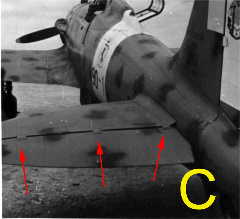
- If you are using tailplanes with balancing horns, you don't need to use any photoetched plates. We can glue the hinges on the lower surfaces but no details must be glued in the upper surfaces of the tailplane. The movable tailplane had only 3 small rectangular hatches to access the fitting bolts, that we can reproduce with very thin plasticard, measurement of 2,1 mm base and 1,7 mm height.
Rudder
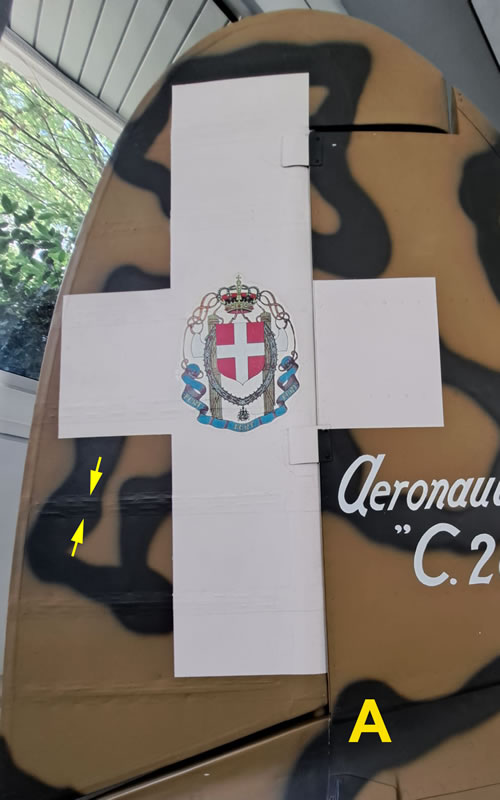
The rudder too, has the oversized stripes and the big raised dots that want to reproduce the knots, but the biggest mistake is that the raised detail of ribs are only 6 instead of being the correct 8 ! (refer to pic A)
In the control surfaces of this kit, all is exaggerated and I fear that even with a good hard sanding, we cannot get rid of this problem, especially for the depression between ribs and the wrong number of some structural ribs.
Looking at the wing surfaces, we spot some engraved lines on the cutting edge of the wings that are to be canceled because they are not present on the actual aircraft.
On the wing’s lower surface, just in front of the radiator intake, we have three circular hatches that weren’t provided with the opening small tag but with a single screw. Photoetched parts 60pe on building section n° 29 are not to be used.
Anyway, a big confusion that is caused by a careless consultation of wartime pictures and technical manuals.
Landing Gear
The landing gear has its torque links casted as a solid part but the actual ones had lightening holes, we had to realize a total of 4 with a 0,5 mm drill bit to enhance the realism of these parts. Unfortunately the many plastic parts from n°59c to 62c that fit the undercarriage legs to their covers, are casted solid and they too need the lightening holes just because through them, ran the brake tubes.
This was a complex assy that was absent from the kit, the modeller should scratch build it with a certain effort considering that it ran down from the wing, reached the wheel fork then split in two different lines that reached the wheel hub faces.
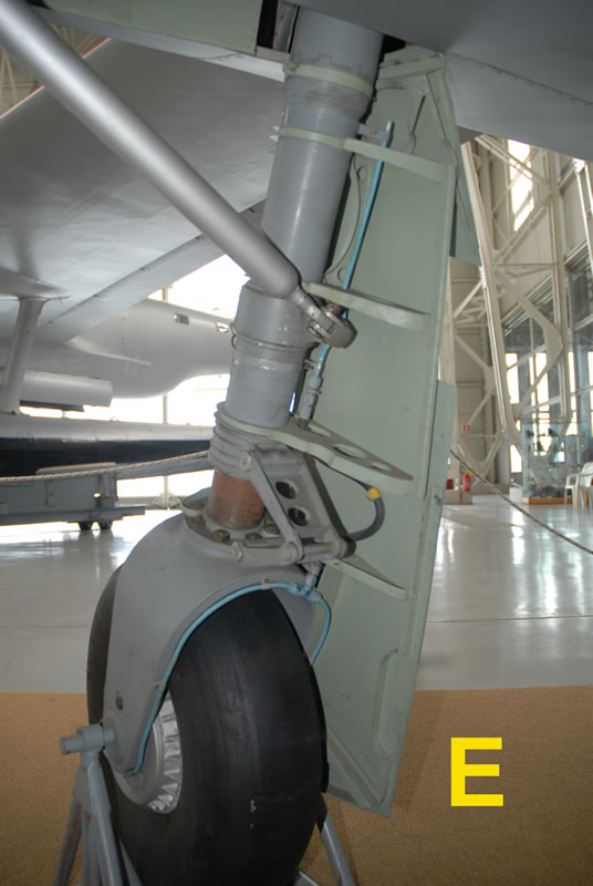
Another big complaint for a kit issued in 2023, is that both main wheels and the tailwheel are missing any inscription on their sides, nowadays a common feature in the aftermarket resin wheels or the one issued by other model companies. The “Pirelli Aeroplano” tyresare not only devoid of any writings but they have an unconvincing and not realistic weight effect.
They are a little bit undersized, the modeller could do their own math taking accurate measurements and considering that the actual ones were a diameter of 600mm, a width of 200mm and offset of 216mm.
The tailwheel is given in 2 versions with the same (correct) measurements and a different hub, tire was 300x100 mm.
-
The kit offers 3D printed instrument panel components and that is a good feature, unfortunately in the pilot's cabin, there is a lot of confusion in the assembly parts.
-
Instructions indicate to fit a San Giorgio C type gunsight but the Folgore planes were fitted only with B type that is present in the sprues but there isn't any indication.
-
In the kit two different oxygen regulators are present, the early “Sala” type and the mid-late german type “Dragher Auer II”. Considering that the kit is for late example aircraft, we should fit the german type that is among the plastic parts along with a small control panel in the instrument panel 3D printed sheet (#5).
-
I wonder why they recommend to put into the cockpit an early regulator instead of the german version, specifically indicated in any mid-late series technical manual for Macchi C. 202.
-
The oxygen tube is also missing, along with the back bulletproof plate that protected the pilot's back, this detail too was a standard issue on late series of this plane.
-
Considering that the kit is offering the option of a wing armament (but probably no airplane of the 8 suggested was so armed), is better to spend few words. Details that are missing from the cabin are two small pneumatic valves with small lever and red discs placed at the lower corners of the windscreen .
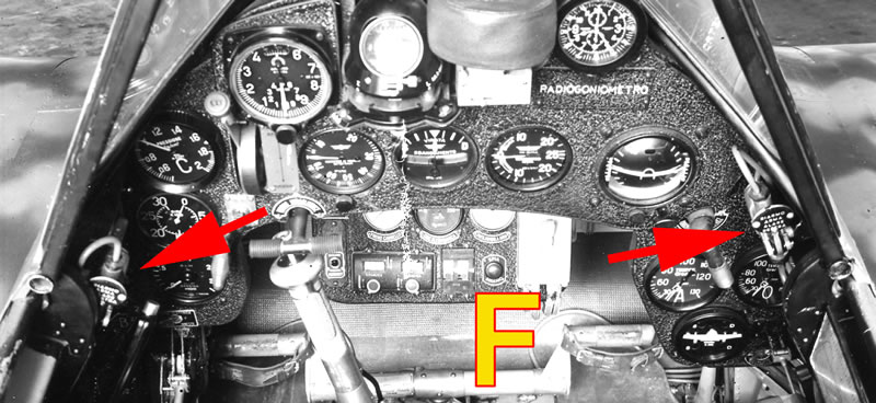
If the aircraft was equipped with nose guns only, they operated the gun safe, while if the aircraft was a 4-guns model, they served to cock the wing guns. In this case, all the 4 guns onboard were put on SAFE/FIRE position via a sole lever placed on the right hand side of the cockpit.
Both the small levers with red discs (all C.202s) and the 4-in-one safe lever (4 guns)must be built from scratch. Please note also that kit’s wing guns, protrude excessively from the wing, actual ones were barely visible and were equipped with a conical muzzle (pic Wguns).
-
Lastly, another 3 details are missing from the cockpit, one is the starting handle that was fitted on the floor, under the pilot's leg's right side. Considering that the model has the “8-shaped” flare exit hatch on the right side of the fuselage, we would need a flare pistol too, fitted at the right side of the pilot's seat (It was the German leuchtpistole LN 24483 starting from Series IX on).Last missing detail is the front bead & sight stick that was placed on top of the fuselage, this detail is needed just because they provided only the one with the ring (part 69c), placed at the base of the bulletproof windscreen.
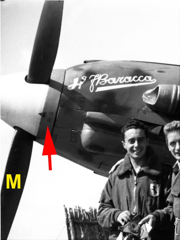
At the first look the propeller's spinner has a weird shape. It seems too long with an oversized front hole. After a careful measurement, the spinner and its backplate have a length of 1,95cm and considering that the entire fuselage is 25,85 cm long, after the spinner is assembled, we will have a total length of 27,8 cm. The actual plane was 8,85mt long and after we divide by 32 we get a value of 27,65cm. It's clear that the spinner is excessively long by 1,5mm that rises to 1,8mm, if you consider that there was a space between the nose and spinner by a little less than 1 cm to avoid any vibrations (so add a further 0,3mm). The front hole is really oversized and this is connected to the using of the Macchi C. 202 preserved in the Italian Air Force Museum as a reference, without knowing that its spinner is not genuine and came from a largely modified C.205 Veltro spinner. I don't see any solution for this problem, just because reducing a large hole on top is really difficult, I just hope that this excess of lengths is limited to the spinner, because if this 1,8 mm excess were distributed on the entire fuselage length, that would be really bad.
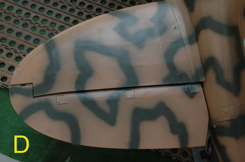
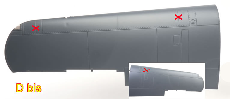
Checking the surface details of the fuselage, it looks like part n°44a, right hand rear engine cover, is afflicted by several errors. First of all, on the lower part there is a circular hatch that was present only on C.205 Veltro, to operate a small tap for thinning the engine oil with fuel in case of a cold start up; it must be puttied over.
The second error is that behind the aforementioned hatch, there is just one cooling louvres but they must be two; considering their shape it shouldn't be too easy scribing a new one.
Last problem is the absence of a hole that allows hot gases from the right machine gun to come out; it must be done with a 1,2mm drill bit following the wartime pictures.
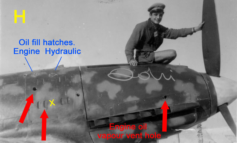
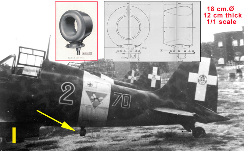
A further hole is missing from right fuselage part 32a, in its front part, upper the exhaust stacks. Here, in the middle of the two rectangular hatches, there was the oil vapours exhaust vent, that we have to drill with a 0,7 bit. Below the tail boom there was the fitting plate of the Direction Finder loop antenna that is completely missing from the kit although the example coded 70-2 was so equipped. Telling the truth, instructions give photoetched parts n°31pe as the fitting plate but wrongly indicates the part n°13a described as a sort of lens for a photo recon version.
DF Antenna must be scratch built or sourced from other model kits.
Another annoying detail is that inside the landing flap and the curved cover that closes the landing gear bay, here are present many of the ugly sink marks used to ease the sprues to come out of the casting blocks.
Every modeller hates to putty over those sink marks but when they are hidden between two landing flap ribs or in the lowest part of the landing gear cover, the task became a real nightmare. Not only but the many sink marks inside the landing gear cover seem as if the plastic was melted; the worst thing is that all the small hatches and details inside the cover are missing. These hatches allowed ground crew to disconnect the engine starter when the start up was actuated via the external handle or to inspect the delicate inner mechanism. The modeller would need to rebuild from scratch all these items, taking advantage of the original manual drawings.
Last details that are really oversized, are all the components of the radio antenna wire, as insulators and photoetched fin anchor plate part 59pe are out of scale.
Engine Bay - What's Missing |
This kit can be built with the exposed engine, and many details are present on both sides. Once assembled, the engine compartment seems to have many “voids” because several parts has not been designed nor included in the kit. The following informations are just hints for those who wanted to build a model with un-cowled engine and complete details.
-
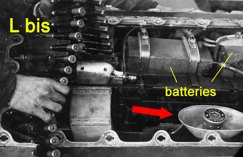
In the left side of the compartment, a large electrical junction tray with circular wire connections must be scratchbuilt (pic I bis).
-
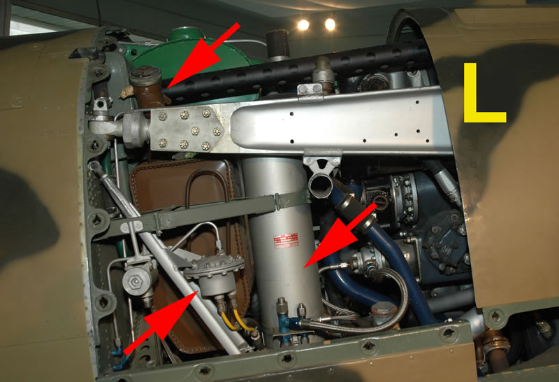
Attached to the fire proof plate there were two “V” shaped bearers that support specific components. Considering that the left bearer correctly shows the two components, we cannot say the same for the right one part n°37c that is supporting nothing. Here real airplanes had the “Iniettore E.C.” that injects fuel in the engine before the start up. It is a sort of small bottle and must be scratch built. Here another component is missing, the bottle for the hydraulic oil and I suggest to build both of them, because that area is really empty.
-
The foldable small stick that should be fitted on the top of the upper engine cowl n°45a, used for compass tuning is missing and must be done with a small plasticard disk and a segment of stretched sprue.
-
On the forward engine right side, the vapour oil tank is missing along with its breather. A tube comes out from the top of the engine, reaches the small brown tank where the liquid oil was recovered and vapours are expelled from a tube (missing and traced in yellow in pic.
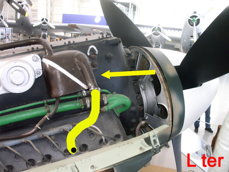
Patience, plasticard and rods are needed here too.
Colour Directions
During the assembly stages, many parts had a color suggestion, some of them are wrong, and modellers should follow the below indications:
-
Oil tank (parts n°31c, 32c and 4c) is indicated in black but it should be painted in semi-gloss dark brown.
-
Landing gear legs are indicated as Grigio Azzurro chiaro 1 (GAC 1) but needs to be painted in semi-gloss medium gray.
-
The retraction hydraulic jacks (52c e 53c) are indicated in GAC 1 but they should be in semi-gloss dark brown with chrome tubes.
-
The nose machine guns cover tubes (7c and 5c) are indicated in a rust color but they should be painted in GAC1.
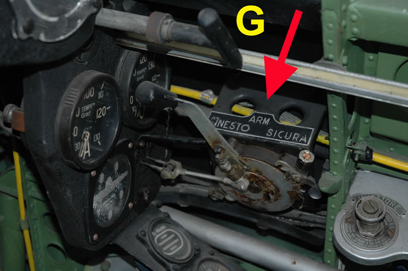
The fuel lever 44pe is indicated in orange but should be painted in aluminum with a yellow knob.
-
The pilot's feet holder (part 13pe) are to be painted in aluminum and not in anticorrosion green.
-
The tailwheel structure must be painted aluminum and not GAC1.
Marking Guide
The kit offers 8 color profiles, strangely all of them have weird panel lines, they are all fitted with the very early style tailwheel while the nose lines, are those of the series III Macchi C.205! Moreover, on the right hand side of the hump, the auxiliary fuel filling cap is repeated, that could induce modellers in some errors. The famous “Smoke Rings” camouflage scheme is provided via a large decal sheet where every single smoke ring is to be applied on a Nocciola Chiaro 4 background. The option is valid for those modellers that don't trust to do this particular camo scheme with the hairbrush but considering that the actual smoke rings were sprayed by freehand, they resulted all different from each other, and so the decals sheet cannot match all the five examples proposed by Italeri.
nfortunately, most of these rings had an incomplete shape, I mean that some don't “close” and some of them stop halfway through (#20, 21, 24, 33 and 34). Overall, no smoke rings are provided to fill the void on the machine gun cowling, behind the spinner and on the canopy.
Stencil and National Marking Decals
There are many imperfections in some subject measurements; maybe this list could be useful:
-
Metal tags # 10, 11 and 12 are really oversized because they are large almost double the size. They are 4mm wide instead of being the correct width of 2,3 mm.
-
White-red engine and hydraulic oil triangles #35 and 36 that are to be placed on the two hatches of part n 44a are greatly undersized, they have a side measure of 1mm while the real hatch is to be 3,2mm (the hatches of the kit are undersized because they are 2,6mm in diameter instead of being 3,2mm).
-
Another white-red oil triangle for the propeller mechanism is missing too, it was to be placed across the spinner and its backplate with a writing “AS”. In truth the “AS” writing is present in the sheet #28 to 31 but there is no indication for where they are to be placed
-
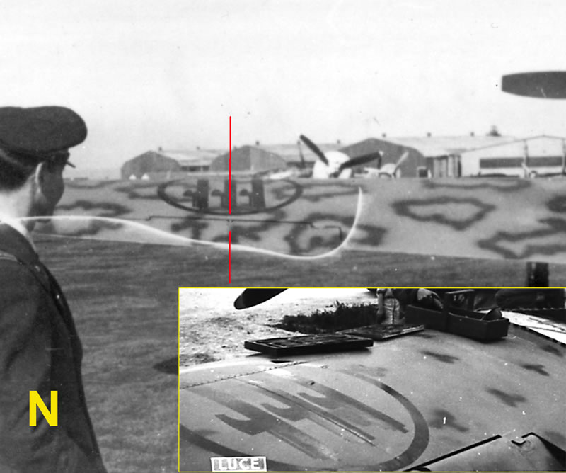
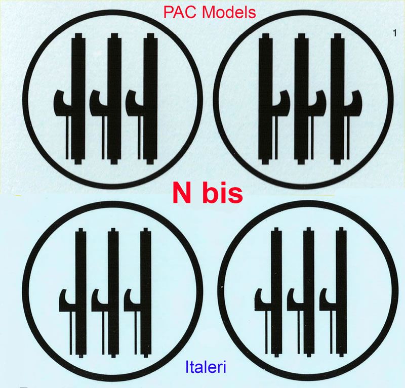
Wing fasces roundels are drawn with really "slim" fasces and small blades. The indicated placement is too much towards the fuselage and modellers who want to achieve a correct position, must put the middle fascio exactly across the wing panel line, that is very close to the aileron hinge.
.
-
The colour of the Matricola Militare and service indications on fuselage and tail are wrong because of their light blue colour. It is a sort of “cyan” and once placed, it resulted too bright. The right color was the so-called “Azzurro Savoia” that actually was a mid-blue Fsc.35095.
-
The last mistake is for the decals #15, a sort of metal tag that shouldn't be placed where the instructions say, and nowhere else. There was confusion with the “Oil dilution for cold start up” tag that was present only on Macchi C.205s but placed elsewhere.
Marking Options
-
96-10: in the color profile, fasces under the right wing are missing, and fasces below the left wing had the blades in the opposite side.
-
84-12: OK
-
70-2: This subject is the one with major mistakes because it is indicated having a camouflaged spinner backplate but the original one was white as the spinner was. After the fall of Fascism on 25th of July 1943, the wing national insignias were deprived of the three fasces. After 2 days, all airplane factories received telegrams with orders to not paint anymore fascist insignia on airplanes and only black circles were painted on wings. So strangely 70-2’s decals, show weird softly-sprayed dark gray rings and this is unexplainable because there are several wartime pictures of this plane, with just black, neat painted circles. Fasces were removed also from the Savoy coat of arms, applied as a decal on the rudder white cross and at that time, there was someone that materially cut away the fasces from the decal. The mistake in the decal sheet is that they indicate to place modified Savoy coat of arms (C version decals #4 and 5) but in these details, fasces’ blades are still present! Last wrong detail is that instructions indicate to place the circular fascio insignia below the windscreen, with this insigna strangely deprived of fascio, leaving just a light blue disc. These are grave errors because if the airplane left the factory without any fascism insignas, nor in the upper and lower wings and nor on the Savoy coat of arms, why should the circulary fascio be applied and later obliterated ? In the pictures of 70-2 the absence of any fascism insigna is evident, just the black circles are present on the wings, there is also a further detail, a small red (black?) number “2” was painted on the landing gear covers and this detail is missing from the kit’s decal sheet. As said, this was the only aircraft among the 8 that was fitted with the DF loop antenna under the tailboom, this detail is absent both in the plastic and in the drawing.
-
396-3: On the decals for this airplane, the decal’s designer wrongly reproduced the “hen and arrow” badge of the right side, he simply “mirrored” the one already drawn for the left side, and so the 396 number (hidden partially by the badge), came out as 693 (mirrored). The result is that we have the two “appendix” of number 3 on the front side and the single appendix of the 6 in the rear, close to the arrow's fin. Modellers should cut these appendixes with a razor blade and paint the correct ones with a small pointed brush.Same mirroring mistake was done on the number 6 that compose the side number 396-3, number 9 was drawn first, then copied and put upside down to have a “6”, without noticing that the breaking of the number is now with the wrong inclination. Please check wartime pictures for reference.
-
353-6: OK
-
356-8: in the color profile, fasces under the right wing are missing. 21° Gruppo was used to paint its “Centaurus” insigna only on the left tail fin surface as seen on all the C.202s deployed in Russia combat theatre. So probably this particular plane too was so configured and decal on the right side of the fin is not to be used.
-
368-1: in the color profile, fasces under the right wing are missing.
-
90-5: OK
This small guide for a correct building of an 1/32 Macchi C.202 stops here, it's not my intention to judge the kit or how to manage it.
My only intention is to guide the modeller across the dozen of peculiarities and the many details of this wonderful fighter plane.
I just wanted to avoid that modellers, who are not keen in Regia Aeronautica camouflage schemes or in Macchi C.202, could continue to make common mistakes or perpetuate wrong considerations that the large bibliography on the C.202 (first of all my old books on the C.202 !) never went into enough detail.
Images and Text Copyright ©
2021 by Maurizio Di Terlizzi
Page Created 19 September, 2023
Last Updated
20 September, 2023
Back to HyperScale Main Page

|
 Home
| What's New | Features | Gallery | Reviews | Reference | Resource Guides | Forum |
Home
| What's New | Features | Gallery | Reviews | Reference | Resource Guides | Forum |