Home
| What's New |
Features |
Gallery |
Reviews |
Reference |
Forum |
Search
Home
| What's New |
Features |
Gallery |
Reviews |
Reference |
Forum |
Search
|
|
|
Henschel Hs 129 by Milton Bell
When Hasegawa announced they were releasing a 1/48 model of Henschel’s Hs 129, a lot of modelers asked, “why?” A lot probably even asked “what?” Obviously, from Hasegawa’s point of view, the answer to the first is “to make money.” The answer to the second is “the Hs 129 is a very early version of the dedicated airborne tank killer and general all around “air to mud machine.” And it’s an important aircraft. The Hs 129 employed all sorts of revolutionary, for its day, adaptations. It had the pilot enclosed in a small, armored capsule with good visibility over a sloping nose. It was so tight inside the cockpit that the gunsight was mounted in front of the windscreen and the engine instruments were mounted on the nacelle of each engine! And the lower cowling of each engine was also armored. But armored or not, the engines were one of the major failures of the aircraft They were generally temperamental and lacked the power needed for an aircraft even as small as the Hs 129 was. As bad as they were, they were a considerable improvement over the Argus engines which powered the early Hs 129A-0 versions. And these were better than those given the test pilots of the prototypes who had nothing good to say of the 129. These early machines were very difficult to fly even in ideal conditions, not to mention combat maneuvers. Only after much modification did the first 12 A-0 aircraft and 16 A-1 versions enter service in 1940.
These first production aircraft carried four forward firing guns as standard armament. They were mounted in the fuselage behind the cockpit and fired through channels on either side of the pilot. Two MG 17 machine guns (7.92mm) were mounted in the lower section. Above them were two 20mm cannon. I’ve always wondered how noisy they must have been for the pilot. This basic arrangement of armament continued through the series. Since the Argus engines were obviously the primary cause of low performance for the aircraft, a decision was made to use the more powerful Gnome-Rhone engines which were available in numbers after the fall of France. Thus was born the Hs-129B which is the subject of the Hasegawa kit. The Hs 129B carried a variety of weapons including several types of bombs carried in a rack under the fuselage centerline and on wing mounted racks. It also carried some impressive large bore cannon carried in pods under the fuselage. The Hasegawa kit offers two choices: a Mk 103 cannon or a Mk 101 cannon, both in 30mm. A later version (still to come I hope) mounted an impressive 7.5cm cannon! Quite a can opener!
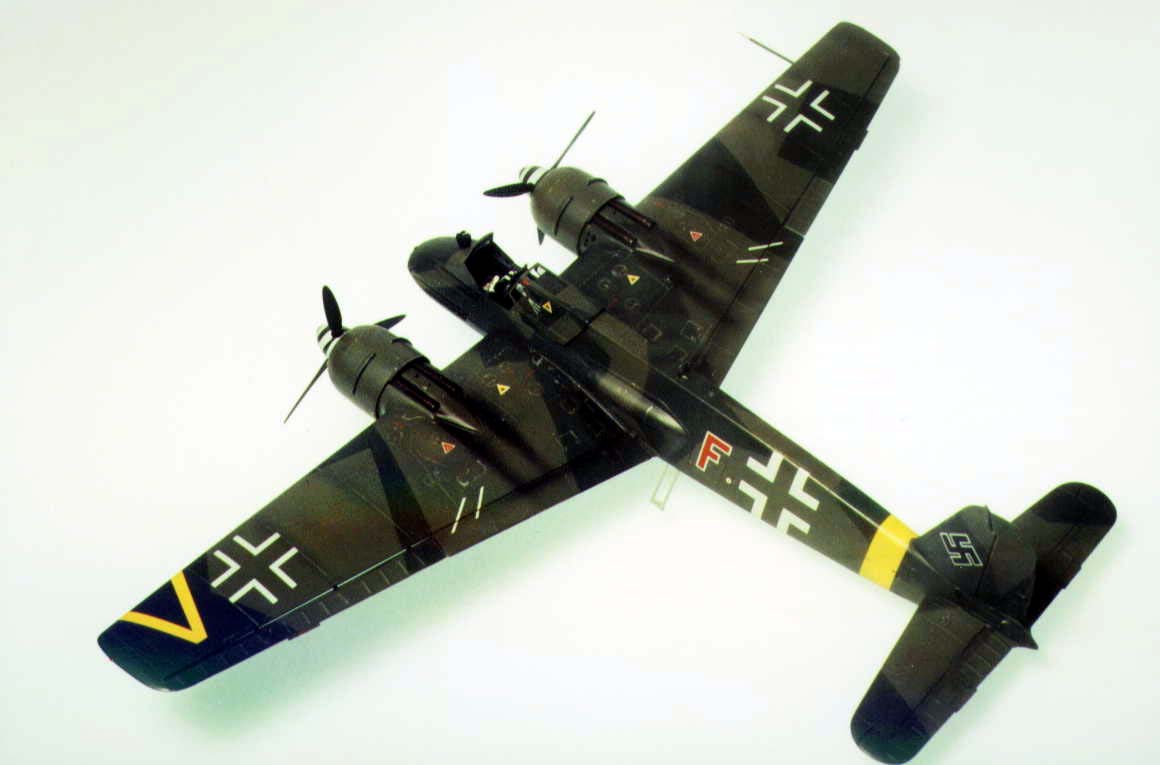
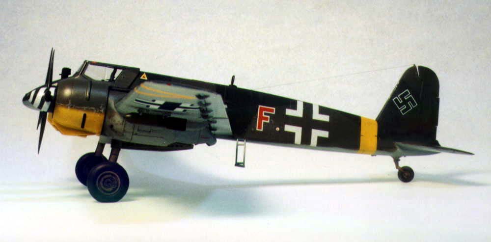
And now for the kit. Hasegawa has produced some really fine kits recently and I think this is one of their best. The fit is good, the detail is clean, and the engineering is very good indeed. The kit is produced in that ubiquitous gray styrene and has some very nice and very thin clear parts that are easy to get off the runner and clean up. There are only two clear pieces; the windscreen and sliding hood portion. Oh yes, there is a landing light. Parts and decals are included to produce either a Mk 101 armed machine of 8.(Pz)SG1 or a Mk 103 armed veteran of 8.(Pz)SG9. Both are in Eastern Front markings of a splinter scheme of RLM 70/71 over 65 with yellow fuselage band. As seems to be the current vogue among Japanese manufacturers, there are soft vinyl caps to hold the propellers in place and these work very well. I like ’em.
Construction of the kit is very straightforward. It begins with the cockpit which holds no surprises. Just be careful of the parts C-28 & 29 which are the inside portions of the 20mm gun troughs. I used the kit decals for the side consoles but painted and dry-brushed the instrument instead of using the decals supplied. Why? Because I like to. I could have used a punch to make individual decal instrument faces and that would have been fun too. The kit seat is in a reclined position (so the pilot could get in or out easily) but there is no articulation indicated on the seat. There is a separate upper armor piece. The armor plate that goes behind the seat has some nice detail that all but disappears when it’s assembled. Be aware that the shoulder straps are fastened to the bulkhead behind the armor and pass through slots which are indicated and are easily opened. I used individual buckles from Eduard and lead foil from dental X-rays for my belts. I painted the belts light gray. The cockpit tub and seat installs easily between the two fuselage halves.
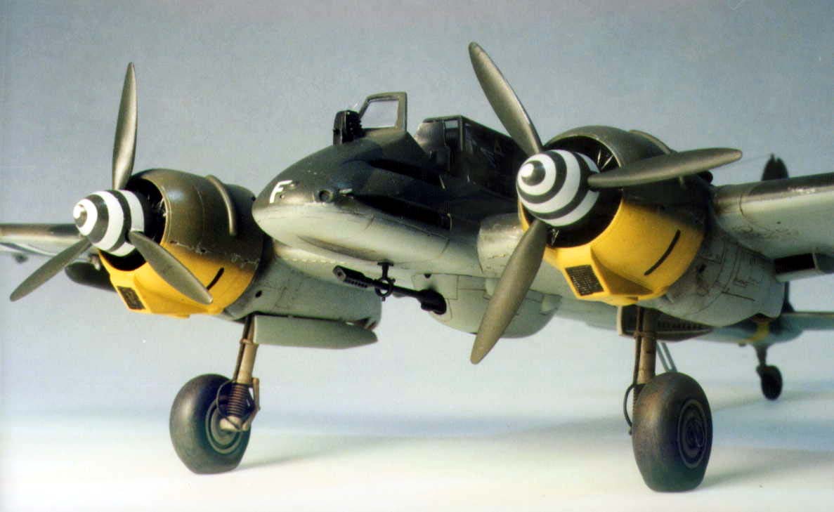
Be very sure you install the two radiators on the underside of the wing before you add the engine nacelles, otherwise, you’ll never get them to fit. Follow the instructions and the fit will be just fine. I had a little problem getting the lower nose cap to fit well (part A6) but a little putty around the edge and some careful sanding and very little detail was lost. The assembly of the kit from here on is pretty basic except for the separate ailerons. Those mounting “hinges” are not all the same so be careful that they are the correct ones before you glue them in. I used Testors liquid cement here since it dries somewhat slower than Tenax and let me correct the alignment. If they aren’t aligned right, the aileron won’t fit, so be careful. I decided to add a floor to the engine nacelles over the carburetor intakes so I couldn’t see through. You can’t see much so it’s your call. It’s an easy job with a little sheet vinyl. Notice that the props turn in opposite directions. Yes, you have to build each prop from separate blades and boss. Looks good when its done though. I painted mine overall RLM 70, black green. That’s the color that will be correct for most Luftwaffe prop jobs. I used the same color for the two small bombs. I added them after I had painted the wing. The wing to fuselage fit was very good. Only a little CA was used on the aft section to eliminate the joint. After I had sanded it down and matched the two surfaces, I rescribed the panel line over the CA joint. I found that the two engine cowlings fit very well but I had to do some trimming of the alignment slots to get them to sit right over the engines. Two exhaust systems are included in the kit but the longer pipes are shown. My records show that some of the 129Bs had the short upturned exhaust pipes. I also chose to widen the end of the exhaust by drilling it out larger than the kit hole.
To get the windscreen in the right position, I used the sliding part as a guide. The fit of both pieces is right on but mistakes can happen. I dipped both pieces in Future a couple of times to get more clarity and protect the plastic. I used some fast setting cement (Weld On #4) to secure the windscreen when I was sure it aligned with the sliding section. It worked fine and there was no fogging. The tail wheel has an oval shaped boss that fits a recessed depression. I would recommend cutting off the small peg and making the part fit the recess. You may have to thin it a little for a good fit.
I completed the kit in, what is for me, a pretty short time—a couple of weeks of evenings. I had no major problems and I hope to build another of these little kits. You will be amazed to see how small the complete model is, especially when compared to a P-51 or a Sturmovik. I even used the kit decals and they worked just fine with a little Micro Sol. Here’s another hint. That little decal that goes on the canopy window is applied to the inside. If you can see the decal film after it dries, just give it a coat of Future and the film will disappear! There is a slight error in the instructions as to where those two little white lines go. They are flap indicator lines and should go across the wing/flap line, not on the wing alone as the instructions show. Just move them back a bit. And watch that step—I applied mine last because I didn’t want to break it off since it extends out at about a 30 degree angle from the fuselage. Also, check your references to see if your model has the antenna mast or the loop.
Besides the seat belts, I added brake lines to my kit. I used some of the fly-fishing no-lead wire and strips of lead foil wound around the gear strut to hold it in place, and it in turn was held by CA. I think the brake lines add to the “personality” of the little model.I painted it with Aeromaster acrylics and used Future as a glossing agent and PollyScale flat for a final finish. This was a fun kit to build and priced in the lower $20 US range, it’s within most modelers budget. I recommend you try one Text and Images Copyright © 2000 by Milton
Bell
|