 Home
| What's New |
Features |
Gallery |
Reviews |
Reference |
Forum |
Search
Home
| What's New |
Features |
Gallery |
Reviews |
Reference |
Forum |
Search
|
|
BENT-WING
NIGHT BIRD
F4U-2 Corsair Built the Hard Way!By Brett T. Green
This is another classic case of "Murphy's Law" of modelling. At the time I built this F4U2, there was no "out of the box" option to build either of the major Corsair night fighter variants. Within weeks of completing this project both Hobbycraft and Tamiya had released their offerings! Oh well, at least it gave me the opportunity to brush up on my modelling skills. Let me share the experience with you.
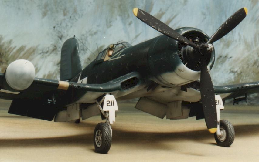
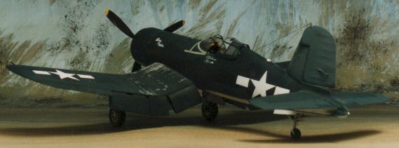
I chose to build "Line Rider", side number 211, an early F4U2 operating in the South Pacific in 1944. This aircraft is described in detail in the accompanying research article on Corsair night fighters. I picked up a 1/48 scale "War Eagle" F4U2 resin conversion set at the sale of a collection a few years ago. In addition to the main conversion parts this $5 purchase included some extras including decal options for early F4U1s and F4U2s; a white metal engine, wheels, flame dampers and bomb racks; and resin flaps.
I began by assembling available references and deciding a subject. "Line Rider" suited my dual criteria of interesting camouflage and markings; and adequate photographic reference. In fact, I had photographs of this aircraft from Port and Starboard sides (a relatively rare situation) in two different books. Also among my references were three drawings from various sources illustrating the markings and camouflage of this particular Corsair. On close comparison with the photographs, all of these drawings were incorrect in various details including camouflage demarcation line and location of fuselage markings.
My approach to construction usually starts with deciding on sub-assemblies. This allows each section of the model to be treated as a project in its own right. The sequence of construction in this case was as follows:
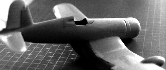
A section behind the cockpit was cut out of both fuselage halves according to the War Eagle instructions. Dry fitting of the resin plug indicated that the fit should be pretty good. The rudder was also removed from the unassembled fuselage halves, and the rear inner surfaces of the fin thinned down with the back of a hobby knife. Now on to the fun stuff!
The cockpits of all F4U1 and F4U2 aircraft had no floor. It consisted of a seat suspended on the rear cockpit wall, and various consoles and equipment attached to the interior fuselage sidewalls. Rudder pedals and control column were mounted on tubular metal control rods running lengthwise along the fuselage. The impression is a busy but roomy "front office". In fact it was so roomy that some pilots needed to use a cushion or two to fully depress the rudder pedals! The cockpit is where most of the detailing effort went. I scrapped the original Otaki cockpit "tub", cut off the side consoles and removed the raised detail. The Eduard details were then undercoated with a gloss grey enamel. This brass set was used to represent switch, quadrant and throttle controls. I further built up the side consoles with styrene block and sheet and added a map case made from lead foil folded around a small block of styrene; and a fire extinguisher made from sprue and a white metal scale railway bolt to represent the spindle and tap. At this stage I marked the position of the side consoles on the fuselage and detailed the inner sidewalls with various widths of styrene strip. Thicker styrene was used to represent the upper lip at the cockpit opening, and this was further enhanced with piano wire for the canopy rails. At the same time I similarly detailed the inner rear fuselage which is highly visible through the large tailwheel aperture. The raised detail on the kit instrument panel was removed, and this part and the Eduard upgrade were painted black. The back of the Eduard acetate instruments were painted white and sandwiched between the kit instrument panel and the brass upgrade. Switches and lights were then highlighted with thinned white, yellow and red paint. The kit seat was replaced with one from the Mauve P40. The profile of the top of the seat was suitably rounded, and Airwaves harnesses added. The Eduard seat mount was attached, and glued to the rear cockpit wall. A small ball of Milliput was allowed to partially dry and then shaped to represent the pilots headrest. Three holes were drilled in the rear cockpit wall and pieces of brass rod glued in place to form the mounts for the rudder pedals and joystick. The side consoles and rear wall (with seat attached) were now glued and painted with a yellowish mix of zinc chromate. Additional equipment including the mapcase and oxygen bottle were now added and details painted as appropriate. The space at the wing root which would be left open with the flaps displayed dropped was boxed in with plasticard. Rudder pedals were fabricated from folded brass sheet Pastel chalks were applied to achieve subtle shading. Finally, the instrument panel was glued into place and the fuselage halves joined. At this point I put the kit to one side for a few weeks!
By comparison, the engine was a simple project. The War Eagle white metal engine looked okay, but was further enhanced with steel piano wire for pushrods and electrical wire for miscellaneous plumbing. The crankcase was painted grey, and the pushrods black. Electrical wire remained in natural metal, and a heavy wash of black was applied to the engine cylinders. After the interior of the engine cowl was painted zinc chromate, the engine was super glued into place.
Various holes for antennae and ordnance were filled, and a number of panel lines rescribed. I also added strip styrene to represent a missing upper engine panel (or cover?). The gap left below the rudder was blanked off with Plasticard.
I decided to use the War Eagle flaps, so I first cut the large flaps from the kit wings and scraped down the edges until they were razor sharp. I then cut five short lengths of brass tube and mounted them just behind the holes for the five machine guns of the F4U2. Milliput was used to position the brass at exactly the right spot, and super glue was flowed over each mounting point for insurance. Holes were drilled for the outer wing bombracks. The wings were then assembled according to the kit instructions. Now was the time to add the most distinctive feature of the Corsair Night Fighter. The radar fairing comes in two halves. These were superglued and sanded to remove any trace of a join. The complete radar assembly simply slips over the leading edge of the starboard wing. After a dry run, the opening was obviously too wide. A few seconds running the resin under warm water allowed me to bend the upper and lower "jaws" of the assembly closer together and, voila! Another perfect fit. Before mounting the wing assemblies to the fuselage, the wing root and fuselage floor section were detailed with strip plastic, painted zinc chromate and highlighted with pastels. Finally, the inner surfaces of the ailerons, left exposed by the missing flaps, were blanked off with plasticard.
The War Eagle flaps were carefully dry fitted then superglued to the upper wing, leaving a significant gap between the lower flap surfaces and the trailing edge of the lower wing. This was not a problem, however, as the Corsair had spring-loaded flap covers which deployed when the flaps were lowered. These were cut from plastic strip and glued into place. I also used stretched sprue to represent a fine hinge line between the covers and the wing trailing edge. I showed these covers open, ie dropped in the same direction as the flaps. Unfortunately, a photograph I saw after completing the assembly showed that these covers actually deployed UP into the cavity when the flaps dropped! Hint - However thorough you THINK you are, you will always find a reference to prove you stuffed something up! I then turned my attention to the rudder. The leading edge of the rudder was built up with plasticard and allowed to dry thoroughly. This plastic build-up was then scraped and sanded to a rounded profile. Holes were drilled to locate a bent piece of piano wire representing the rudder trim tab actuator. The hole in the bottom of the rudder was blanked off with plasticard. The rudder assembly was then ready to be glued, slightly deflected, to the tailfin.
The rear undercarriage was detailed with the Eduard items. This significantly enhanced this overly simple part of the kit. Eduard rear undercarriage doors further improved the impression.
I decided to use the Falcon Birdcage canopy instead of the conversion part. Prior to gluing the forward canopy section in place I scratchbuilt the gunsight assembly with plasticard, acetate and brass rod, plus clear acetate for the pilot's armoured glass. I also added the pilots dashboard and gunsight crashpads by thinly rolled pieces of Milliput. When these had dried, been assembled and painted, I added the Falcon canopy. Except for the
undercarriage, all remaining bits were glued into place, including the accessory bombracks
and flame dampers. After a quick run over with a little putty and sandpaper, the model was
ready for paint I paint using acrylics and a Testors airbrush. Usually. In this case, because I wanted to represent heavy scuffing and paint flaking, I painted an undercoat of Tamiya enamel Chrome Silver. This will allow me to chip away the acrylic topcoat revealing "bare metal". When I am painting a light coloured camouflage scheme, I pre-paint panel lines in a dirty brown-black mix. After the application of silver to selected sections of the aircraft I sprayed this dirty mix over panel lines on the lower part of the aircraft. I then sprayed the three colour US Navy scheme using my own mixture of Tamiya colours. I mixed the colours in the paintcup as I was going, which allowed me to come up with an authentically patchy finish. I then sprayed a heavily thinned dirty brown black over some of the more prominent panel lines. Weathering was completed by "chipping" the acrylic paint on the walkways and leading edges with a hobby knife. Patience is a virtue when you are doing this. It is easy to overdo the effect, so be restrained - sit back and review progress often. Decals came from a variety of sources. As seems usual, the kit decals were not the right size, or quoted in the correct position. I sprayed a Gloss Coat to surfaces about to receive decals. Decals were then applied using Micro Super Set. Hint - Always check references for correct camouflage and placement of markings
The undercarriage was glued into place, antenna line installed and sliding canopy section masked and sprayed. A final dullcoat and the project was complete. All in all, this was another challenging project in which I tried many techniques for the first time. Despite the complexity and length of building time, I enjoyed the project and obtained the satisfaction of completion at the end of each project phase.
Article and b&w photograph Copyright 1996 by Brett Green.
|
 When the fuselage
halves had well set, the resin plug for the mid upper rear fuselage was added. Either by
skill or fluke (personally I believe the latter) the fit was perfect. No filler was
required.
When the fuselage
halves had well set, the resin plug for the mid upper rear fuselage was added. Either by
skill or fluke (personally I believe the latter) the fit was perfect. No filler was
required. 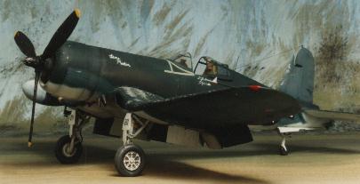 Otaki provide a pretty
good representation of the robust and complex Corsair front undercarriage. I added
brakelines and True Details diamond pattern tyres and wheels. Although the flattening of
the tyres is probably exaggerated, the detail is superb; and anyway the War Eagle white
metal examples were too narrow AND too large in diameter. Like a very big bicycle tyre!
Otaki provide a pretty
good representation of the robust and complex Corsair front undercarriage. I added
brakelines and True Details diamond pattern tyres and wheels. Although the flattening of
the tyres is probably exaggerated, the detail is superb; and anyway the War Eagle white
metal examples were too narrow AND too large in diameter. Like a very big bicycle tyre!