|
|
|
F-14A
Tomcat |

Hasegawa's
1/48 scale F-14A Tomcat and
Black
Box's F-14D replacement cockpit
are available online from Squadron.com
In this day of after market resin
cockpits for every new kit to be released, finally someone has started
paying attention to the kits that are not so new, but just as deserving
of the attention. The company is called Black Box. They have
begun releasing a series of full resin replacement cockpits for a number
of great older kits including Revell's A-6E, Hasegawa's
"Teen Series" (F-14A/D, F-15C/E, F-16B/C, and F-18C/D), Monogram's
"Century Series" (F-100D, F-101B, F-102A, F-104G, and F-105G),
and more. All of these kits are great kits in their own right, but some
of them are pushing 20+ years old and are starting to show their age in
the lack of state-of-the-art details. These Black Box cockpit
sets are just what the doctor ordered to give these kits a real lift.
The Hasegawa F-14 kit has been
out for over 15 years. Built out-of-the-box, it makes a very respectable
model of the Tomcat. The timing of the release of the Black Box
F-14 cockpit set could not have been better as I had just started work
on some Hasegawa F-14 kits. It was a natural to want to use the
cockpit set in these models I was just starting to build. While I had
already gone to the trouble of fixing Hasegawa's cockpits pieces
to better fit the kits, I had not done any extensive detailing or
painting, yet. So, I tossed the kit cockpits out the window and decided
to use Black Box cockpits instead.
I acquired my Black Box F-14
cockpits within days of seeing one at a friend's house. I've seen many
resin cockpits, but the level of detail in this Black Box set
took my breath away. I could not believe the wealth of details that it
provided, on the instrument panels, on the side walls, on the back
walls, and even on the floor! And, I could not wait to have a cockpit
set for my very own. As I was actually working on three Hasegawa
Tomcats simultaneously, I acquired three of the set. Then, I acquired a
couple more sets to put away for future projects. After all, you can
never have too many detail sets.
Black
Box Tomcat Cockpit Set
|
All the Black Box cockpit sets
are marketed in hinged plastic boxes. Packed neatly inside the F-14
cockpit set box are twenty pieces of resin. One is the large cockpit
tub, wrapped in a piece of foam. The rest are all the detail pieces to
attach to and around the cockpit tub. These are contained loosely in a
small zip-lock storage bag. Because some of the resin pieces are molded
with two pieces together, the actual part count for the detail set is
twenty-six. There is no piece of the original kit used inside the
replacement cockpit from Black Box.
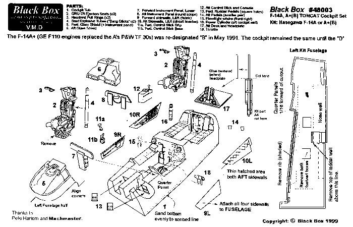
A small folded instruction sheet and the
front cover artwork page finish out the packaging. The instruction sheet
is a single exploded view drawing of the entire cockpit set. On the
backside of the paper are text instructions outlining the process to
modify the Hasegawa kit for the replacement cockpit. Where Black
Box excels at resin, they are somewhat lacking on making clear
instructions. I have included pointers in this writing to help clarify
the proper placement of some of the pieces. Read on...
The parts are numbered in the directions
from 1 to 18. They break down as follows:
- #1 is the main cockpit tub.
You have to see this tub to appreciate it. There is detailing just
oozing from every corner of this piece. This includes not only the
instrument panels, but also the area below the instrument panels, on
the rear walls, and up where the pilot's feet would rest. The floor
of a Tomcat is not just a flat slab. This tub correctly captures the
stepped floor.
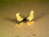
- #2, #3, and #4
assemble together to make the ejection seats. There is two of each
part. #4 is the rocket tube that attaches to the rear of part #2
(the seat). I am unsure why they made this separate from the seat.
The amount of flash on part #3 (the overhead ejection rings) was
going to be a nuisance to remove without breaking the pieces, so I
replaced these pieces with the ejection rings from the kit. The kit
ones looked as good and were flash-free. While cutting free the kit
ejection rings, I also cut free the lower ejection ring that goes
between the pilot's (or RIO's) legs. Black Box missed these
items in their set. My only real complaint is that the seats have
nearly identical seat belt layouts. They are different from each
other, but the difference is not pronounced enough in my opinion.
This is especially true for the shoulder harnesses on the seat
backs.
- #5 and #6 are the front
and rear main instrument panel hoods (respectively). Each has the
upper main instrument panel instrument details molded into the rear
side. #7 and #8 are the lower portion of the front and
rear main instrument panels (respectively).
- #9(L/R) and #10(L/R)
are the front and rear side wall detail pieces. These are
wonderfully detailed and correct. They are also sorely needed as the
Hasegawa kit has no molded side wall detailing.
- #11(A & B) assemble the
make the front control stick. These are extremely fine and a little
tricky to assemble. I needed to check my Tomcat documentation to be
sure I got them assembled the correct way.
- #12 is the center pedestal for
rear cockpit holding the RIO's radar control grip.
- #13 (2 pieces) are the front
rudder pedals.
- #14 (2 pieces) are the rear
cockpit floor footrests. They mount on the rear cockpit floor with
the short side down. The instructions do not label them as left and
right, but they do have a left and right placement. Looking at them
closely, there is a small dimple in the upper corner of each. These
rests hold the RIO's microphone and intercom switches and that
little dimple is the actual switch on each footrest. The dimple on
each foot rest should be on the inboard sides of the rests when they
are mounted to the cockpit floor.
- #15 and #16 are various
cockpit details that should have been molded in place in the cockpit
tub but were not. Attach them as shown in the instructions, although
the location of part #16 is not real clear. I decided to leave it
off, as the rear wall of the rear cockpit (where the instructions
seem to indicate it goes) had no real place to put it. I felt that
leaving it off was safer than putting it in the wrong location.
- #17 is the rear decking in the
back of the cockpit, where the canopy hinge is located. The
instructions say to use a piece of the Hasegawa kit to create
the lifting plunger for the canopy. For added strength, I decided to
use comparably sized brass wire for this part.
- Lastly, #18 is the pilot's
throttle control. Black Box kindly molded
"protectors" into the slag of this part to help keep the
fine "neck" portions from being broken off in the
packaging. Trouble is, they are so fine that I broke them the first
time a handled the part after removing it from the slag. A better
approach is to just remove the "necks" and drilling some
small holes in the part. Then use some fine brass wire to mount the
part and represent the "neck" of the throttles. I used
some .005" brass wire for the job.
You can check out various F-14 cockpit
photo reference pages for more details concerning the accuracy of this Black
Box set. I posted an extensive set of Tomcat cockpit pictures in the
Walk Around section of ARC.
But, take my word, the set is extremely accurate. At the time I was
working on these Tomcat cockpits, I spent an entire morning
photographing the cockpit of a real F-14A. I was amazed at the level of
accuracy in this Black Box cockpit set.
I have read many kit construction
articles over the years where the author states he/she used some resin
cockpit in the model being discussed. But, they don't often elaborate on
that point. When they do mention some of the construction involved with
the resin cockpit, it is usually buried in the rest of the text and hard
to find. I wanted to write something more about just the construction
and usage of the resin, itself. For a complete review of the
construction of my Tomcat(s), look to future postings dedicated to them
where I only mention their resin cockpits in passing.
The first trick to any resin set is to
remove the resin parts from their sprue, also known as slag.
I use one of four ways to accomplish this task.
- Sand Paper and Elbow Grease -
Lay sand paper on a flat surface (gritty side up) and rub the resin
part on the paper to sand off the slag. A friend of mine uses a belt
sander to accomplish this task. Where I might spend twenty minutes
on a part using sandpaper, he spends twenty seconds. Beware, though,
the belt sander is so fast that overdoing the sanding is real easy.
Make sure you are in control of the part and constantly check to see
when you have removed enough slag from the part. Dust control is
also a big concern using the belt sander.
- Scribe, Bend, and Break - With
a "scribing tool" or an X-acto knife, score a line
along the edge of the detail part. Then, gently bend back on the
slag. Resin is usually rather brittle and the scored line acts as a
weak point in the resin. The part snaps free along the scribed line.
Depending on the thickness of the slag, you may need to run the
"scribing tool" or X-acto knife along the part
several times to make a deep enough score line to insure the slag
breaks off cleanly.
- Saw Blade - Using one of
several styles of saw, cut the parts free of the slag. I make use of
all the following at different times for different tasks -- an X-acto
razor saw, a Dremel radial saw, and a jeweler's saw.
- Carving - Each of the previous
three methods assumes there is a straight edge for the slag to be
removed along. Occasionally, a detail set will have a piece that is
not straight on any side and therefore can not be attached to the
slag with a straight edge. When this happens, your only real choice
is to get out your trusty X-acto knife with a #11 blade and
start carving off the slag along the needed line.
Each of these ways is tailored to a
specific type of slag removal. I used all of the first three ways of
slag removal to work on this cockpit set. None of the pieces in this Black
Box set required the fourth style. Each of these ways is a bit
tedious and prone to trouble, so I will try to elaborate more about them
as I go.
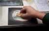
The first method, sand paper and
elbow grease, is used when removing large amounts of slag from the
bottoms of large pieces, specifically the main cockpit tub in this set. Black
Box was nice in providing a clue to how much resin needs to be
removed as they have a molded in line running around the outside bottom
of the main cockpit tub. I needed to sand the bottom until this line is
reached. Sounds easy, huh? Guess again.
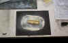
I start by laying down a piece of heavy
grit wet-and-dry sandpaper on a flat surface, grit side up. I use 180
grit paper. Finer grit takes too long to sand and heavier grit leaves
too rough of a surface when I am done. I regularly clean the paper as I
am working to remove the resin residue, brushing it into the trashcan.
This residue gets under the resin piece and interferes with the sanding
if I just leave it alone. Also, some of the residue can get ground into
the paper and form a smooth surface on the paper. A scrape from an old X-acto
blade removes this crusted residue and allows the sandpaper to continue
its job.
 |
There are two choices here -- sanding
wet or sanding dry. Particles in suspension making the
sanding go faster is bull-cr*p, so do not make any decision on those
grounds. It simply comes down to dust control and the messiness of the
task. Wet is not dusty, but it is very sloppy. Dry is less sloppy, but
is very dusty. Bear in mind while you are deciding, too, that resin dust
is a cancer-causing agent. Get a hold of a safety placard for the stuff
sometime and then turn white when you think of all the times that you
have breathed this stuff while modeling.
Anyway, I prefer the dust to the slop.
So, I sanded the cockpit bottom dry. To keep from breathing the dust, I
did the sanding in my paint booth. Like the fan removes the paint fumes,
it also removes the resin dust in the air. I also wear a dust mask to
protect me from anything the paint booth fan missed. I move the resin
piece in a small circle on the sandpaper, taking care to consciously
watch how hard I press on the piece. I needed to continuously check and
recheck the line running around the cockpit tub to see when I was
finished. All three of my cockpits were molded with more slag on one
side. This presents a challenge to control my pressure on the piece and
sand only one side without letting the other side lift off of the
sanding surface. I also needed be careful not to rock the piece as I
moved it on the sandpaper. Rocking the piece would cause a non-flat
bottom on the piece and complicate mounting it squarely on the nose
landing gear well.
That last sentence brings me to the real
pitfall of this sanding process. If I remove too much resin, the cockpit
sits too low in the fuselage and can complicate the interaction of the
other pieces of the set that are counting on the cockpit sills to fall
at just a certain height. If I don't remove enough resin, the cockpit
will not fit into the fuselage at all. With practice, this all can be
mastered, honest! It just takes time and practice, practice, practice...
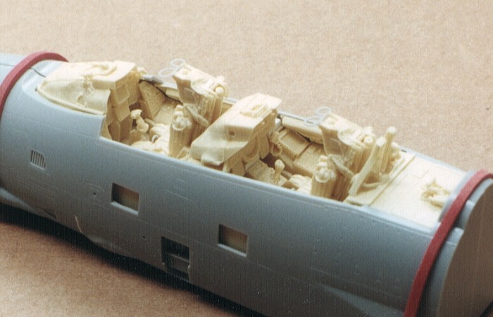
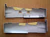
With the cockpit sanding done, I needed
to turn my attention to the kit fuselage. The Black Box
instructions say to remove some interior portions of the fuselage side
to make clearance for their cockpit pieces. See the pictures to the
right. The one shows what I needed to remove and what it looked like
after removal. The other picture shows the view from the outside with
the Black Box cockpit fitted inside the fuselage. The side of the
resin cockpit replaces the portions that were cut out of the fuselage.
An alternate approach that a friend of
mine used on his Black Box set would be to machine out holes in
the side of the Black Box cockpit piece. The holes fit over the
things inside the Hasegawa fuselage that Black Box is
saying to remove. The decision comes down to which way you are most
comfortable at working and what tools you have available to do the work.
With the cockpit bottom sanded and the
fuselage modified, I assembled the kit nose wheel well and tacked it
onto the cockpit bottom with a small dab of super glue to test the fit
inside the fuselage. When I was satisfied that the fit was correct and
the wheel well placement was correct, I applied liberal amounts of super
glue and accelerator to firmly attach the cockpit to the nose wheel
well. Note that normal plastic cement will not work on resin. Super glue
is the least messy way to deal with attaching resin parts to each other
and the styrene kit parts. Two-part epoxy can also be used, but that is
more mess than I ever want to get into unless I am left no choice.
 |
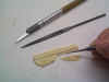
With the cockpit position finalized, I
could turn my attention to the next items in the assembly. For me, these
were the side walls. These are molded with the slag running down a very
thin edge. The method I use for removing this type of slag is the scribe,
bend, and break method. I use a Squadron scribing tool to
score a line down the edge of the piece. Depending on the thickness of
the slag, I may retrace the scribed line repeatedly to make a deep
groove. In the case of these side wall pieces, repeated passes of the
scribing tool was not needed. The scribed line acts as a weak point in
the resin and by gently bending the slag back from the scribed line, it
snaps. This is generally a pretty clean break, but I will use an X-acto
knife and/or file to finish off the resin part and make the edge smooth
and regular.
I then assembled the fuselage with the
cockpit in place and rubber banded the fuselage together. Verifying the
cockpit was positioned correctly, I tacked the side wall pieces into the
fuselage interior with a small dot of super glue. Some of the side walls
are a bit large for the cockpit areas they fill. I needed to trim them
down a little on their ends to make them properly fit in place. When all
the side walls were in place and I was certain they were correctly
located, I carefully disassembled the fuselage and applied more super
glue to firmly attach the side walls.
With all the side walls installed into
the fuselage, I started work on the detail pieces that needed to be
added into the cockpit tub. There are quite a few details to be trimmed
off of their slag and added inside the cockpit tub. A few of these left
me scratching my head and wondering. They could easily have been part of
the main tub when it was cast. That would have eliminated my need to add
them (and potentially mess them up).
Most of the detail pieces come attached
to solid slag blocks in one way of another. I find the saw blade
approach works best at removing pieces from slag that are attached in
this manner. For very tiny or fragile pieces, I find the best saw for
the job is my Dremel high-speed motor tool. I mount a tiny radial
saw blade in the tool and carefully cut the parts free of their slag. I
have found that this style of cutting provides the most accuracy on the
cut with the least chance of damage to what can be very fragile pieces.
Of course, this cutting is not without
risk. Dremel stopped selling this saw blade after a few
unfortunate people lost fingers using it. The blade is extremely
effective at cutting any soft material, including skin and bone. Take
precautions when using this tool/blade combination. If the blade binds
up and jumps, do not have any fingers in its way. A saw blade to fit
your Dremel tool is still available from companies other than Dremel.
Once the pieces were cut free of their
slag, I attached them into the cockpit tub in the locations indicated on
the instruction sheet. See the descriptions with the individual parts
(above) for any specific notes regarding the placement of the detail
parts within the cockpit tub.
In the case of the main instrument
panels, I assembled the rear panel (parts #6 and #8) and left the rest
as separate pieces (parts #5, #7, and #12). I kept these out of the
cockpit tub pending the completion of the painting of the parts. On dry
fitting the pieces into the cockpit, I found the rear instrument panel
sat too flat in the cockpit tub. So I added .060" strip
styrene at the place where the rear portion of the panel rested. This
had the effect of rocking the instrument panel so that the instruments
faced the RIO's face, not his belly button.
 |
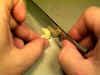
The final things to assemble after the
detail parts were all attached into the cockpit tub were the ejection
seats. Here I also used the saw blade approach to slag removal.
This time, though, I used an X-acto razor saw. This style of
cutting is better than the Dremel cutting method for larger
pieces like the seats as the slag portions are larger and more prone to
binding the Dremel blade. I like my fingers attached to my hands
where they are, so this less volatile cutting method works better. Also,
the seats are more regular in shape and can be held without as great a
chance of breaking them.
With all the seat pieces free of slag, I
assembled the seats and placed them aside to wait for painting.
When I completed assembling the ejection
seats, I was done with the integration of the Black Box set into
the Hasegawa F-14 kit. All that was left was painting the
details, but that will be a different posting.
As I said at the start of this article,
it is about time that some manufacturer pays attention to these older
kits. Black Box definitely has their act together and is
producing some of the best after-market cockpit detail sets I have had
the privilege to use. I hope to see them continue to grow their line.
Go
to Part Two - Painting the Cockpit for Effect
Go to Part Three - Tomcat Construction
Go to Part Four - Painting an NSAWC Tomcat
Model, Description and Images Copyright ©
2001 by David Aungst
Page Created 27 June, 2001 Home
| What's New |
Features |
Gallery |
Reviews |
Reference |
Forum |
Search
Home
| What's New |
Features |
Gallery |
Reviews |
Reference |
Forum |
Search