|
Messerschmitt Bf 109K-4
Detailing
the 1/48 Scale Hasegawa Kit - Part One
by
Frank C. Crenshaw
|
|
|
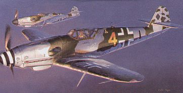
Boxart from Hasegawa's 1/48
scale
Messerschmitt Bf 109K-4 |
The release of the Hasegawa Messerschmitt Bf
109K-4 kit
in 1/48 scale was great news for the 109 enthusiast. Both Brett Green and
Floyd Werner
did excellent buildup reviews that show just how great this new kit
really is and why it was worth the wait!. I have been working on
a few other projects lately but decided to drop them for the moment and
build one of these magnificent kits. I really like Bf 109s and like Floyd
Werner, have been looking forward too actually having one since first
seeing the 109G kit had a sprue marked "G/K"..
Both Brett's and Floyd's excellent reviews cover the the main features
of the kit, installing an after market cockpit, and painting in very
good detail. Thus, my article will focus on adding some detail
to the airframe. Just so there are no misunderstandings, I
am in no way saying that this kit has "problems". In fact, it is
just drop dead gorgeous right out of the box. But I did find
some things that fairly easily improvements to the model,
so here we go.
|
Building
From The Bottom Up...
|
When I do extra work to a kit I try to
start from the wings and move up. The cockpit is almost always the last
thing I do. This is because I enjoy cockpits and tend to do them quickly - I almost always have enough energy to finish a cockpit. Also- and more
importantly, I am less likely to screw up my cockpit detail canopy
while working on some other part of the plane so I save the cockpit until
almost the very last.
Landing
Gear Bays
 Now this kit has the same wing and wheel wells as the
109 F/G kits. In reality - due to increasing weights the design was
changed and larger wheels and tires were added starting with
the G-5. The increase in tire size made it necessary to add a bulge
in the wing to allow the larger wheels to retract. Now this kit has the same wing and wheel wells as the
109 F/G kits. In reality - due to increasing weights the design was
changed and larger wheels and tires were added starting with
the G-5. The increase in tire size made it necessary to add a bulge
in the wing to allow the larger wheels to retract.
The tire
size increased again on some models of the 109G-10 . These even larger
wheels necessitated a large wing cutout in the wing, which
actually caused the removal of a spar. I assume that the later style bulge
was added to accommodate this spar removal and probably serves as some
sort of structural reinforcement. Will Reipl sent me a fantastic
picture of a 109G-10's wheel well that features this later style bulge.
Good photos of the 109G-10/K type bulge can be also found in the Aerodetails
book on the 109G. The main feature of this type of bulge installation
is the large cutout in the wing and the obvious gap between the bulge
fitted to the top wing and the actual wing surface. This turns out to be
very easy to replicate. The Hasegawa bulges are extremely thin
right out of the box.
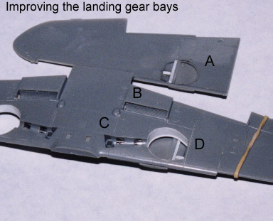
To model this this cut out, I simply drew an outline on
the top wing surface where the bulges fit. I then thinned this area down
- being careful to stay in the boundaries. Once the plastic was paper thin
I drew and outline of the wheel well on the inside wing using the wheel
well as a guide. I then penciled in the cutout and drilled many small holes
within this cutout. I then carefully cut the cutout using a sharp scalpel.
I actually cut a little too much off mine - still it looks pretty good
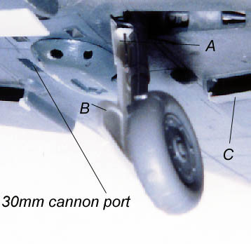
(A). I then added rib detail following
my references. Since I was adding detail to the wheel well,
I decided to open the front cowling flaps some (B).
These flaps are shown in a slightly open position in many pictures. I cut
the flaps out and glued small strips of styrene to the ends of each one.
This represents the side lip that is very obvious on these flaps when they
are in the open position. I also boxed in the radiator bay since the open
flap would make this bay visible. I then cut the access holes in the landing
gear bay out and added some lead wire lines to simulate the lines that
are visible through these holes on the real plane (C).
On every Hasegawa 109 kit I have the molded kit well does not fit to the
the bottom of the wing very well. There is always an enormous gap. Over
on the Hyperscale discussion group. Lynn Reitger expressed a novel
and extremely easy way to solve this problem All you have to
do is cut out .005 strip and dry fit it into the well. With some
fiddling and trimming, it is easy to make the styrene fit the walls
of the well (but it will still stick out of the bottom of the wheel well).
I then glued the styrene in place using some Ambroid pro-weld and let dry.
Once dry I trimmed the excess from the wing bottom (D).
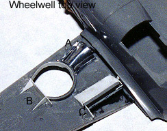 Over on the top side of the bottom wing, I glued a piece of
sheet aluminum over my lead wires (A).
I added a new end piece to fill fill up the gap and to make adding the
auxiliary door retraction mechanism easier (B).
I then boxed the front of the wing radiator bay using sheet styrene
. Since there is no detail for the radiator backside, I made
a casting of the radiator insert and glued it on to a .015 strip. This
piece was then carefully trimmed and fitted in the rear of the radiator
well (C). I also built up the fuselage
side (see D on the Nose section) and made a wall to completely box this
area in. Now I have a completely boxed in radiator bay ready to super
detail. Over on the top side of the bottom wing, I glued a piece of
sheet aluminum over my lead wires (A).
I added a new end piece to fill fill up the gap and to make adding the
auxiliary door retraction mechanism easier (B).
I then boxed the front of the wing radiator bay using sheet styrene
. Since there is no detail for the radiator backside, I made
a casting of the radiator insert and glued it on to a .015 strip. This
piece was then carefully trimmed and fitted in the rear of the radiator
well (C). I also built up the fuselage
side (see D on the Nose section) and made a wall to completely box this
area in. Now I have a completely boxed in radiator bay ready to super
detail.
External
Stores Rack
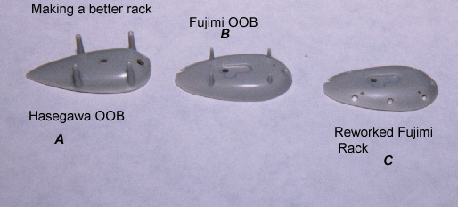
According to my references the external stores rack supplied with the
kit is inaccurate in its overall shape (A).
It is far too narrow and pointed at the tail end, is missing
several access holes, and his extraordinarily overdone tank supports. The
Fujimi rack is accurate in overall shape but is also missing the access
holes, and is shaped wrong around the edges (B).
I took a Fujimi rack and reshaped the edges with a round needle file and
drilled the access holes (C). Since
all 109s used pretty much the same rack I made a mold of this shape for
future projects.
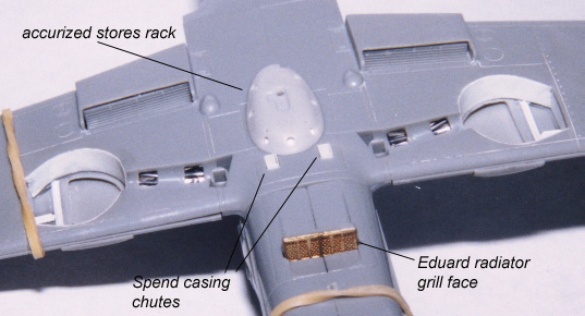
The photo
(above) illustrates most of the changes I have made to the lower
nose and landing gear bays. I swiped the radiator grill from an Eduard
Set designed for the Fujimi kit. The spent shell chutes were constructed
from .005 strips of sheet styrene.
Slats
 The 109K featured free floating Hadley Page type slats on the wing
leading edge. According to Hyperscale regular and 109 expert Vincent Kermorgant,
the slats were constructed from steel on the 109K. These are the
same slats fixed to all versions of the 109. Photos show these slats either
partially open, fully closed, or a combination of both. Since the 109K
was a tail dragger, these slats could not fully deploy on the ground due
to the pull of gravity. They will fully deploy if the tail is pulled
up level however. There is a picture in the Squadron 109 part 1 book that
features a 109E-1 with it's tail raised up for bore sighting of its guns.
This planes slats are clearly fully deployed as one would expect.
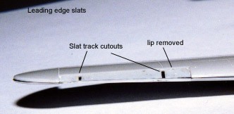
Careful study of pictures that show the leading edge slats show small cutouts
in the slat recess. I suppose these cutouts are for the rails the slats
move on. The cutouts are not present on any of the Hasegawa 109F - K kits
but are fairly easy to add . I used the plans on page 81 of the Aerodetails
109G book to determine the location of the cutouts. These tracks
are surprisingly thin - about the thickness of twice that of a razor saw
blade, so go slowly and use two consecutive cuts to get the thickness correct
. Another noticeable feature is that the slat recess bends
smoothly with the top of the wing. The kit has a molded in
lip so that the slats can be glued shut. I decided to
display my slats partially deployed. I used gap filling CA and accelerator
to remove the prominent lip found on the kit. The 109K featured free floating Hadley Page type slats on the wing
leading edge. According to Hyperscale regular and 109 expert Vincent Kermorgant,
the slats were constructed from steel on the 109K. These are the
same slats fixed to all versions of the 109. Photos show these slats either
partially open, fully closed, or a combination of both. Since the 109K
was a tail dragger, these slats could not fully deploy on the ground due
to the pull of gravity. They will fully deploy if the tail is pulled
up level however. There is a picture in the Squadron 109 part 1 book that
features a 109E-1 with it's tail raised up for bore sighting of its guns.
This planes slats are clearly fully deployed as one would expect.
Careful study of pictures that show the leading edge slats show small cutouts
in the slat recess. I suppose these cutouts are for the rails the slats
move on. The cutouts are not present on any of the Hasegawa 109F - K kits
but are fairly easy to add . I used the plans on page 81 of the Aerodetails
109G book to determine the location of the cutouts. These tracks
are surprisingly thin - about the thickness of twice that of a razor saw
blade, so go slowly and use two consecutive cuts to get the thickness correct
. Another noticeable feature is that the slat recess bends
smoothly with the top of the wing. The kit has a molded in
lip so that the slats can be glued shut. I decided to
display my slats partially deployed. I used gap filling CA and accelerator
to remove the prominent lip found on the kit.
Improving
the Nose
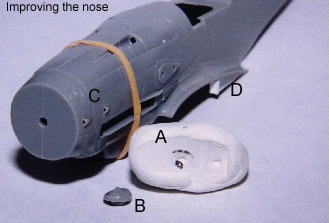 One of the more difficult things to fix on this kit is the molded
vents on the nose. These vents are very small and drilling them out
is not an option! I was poking around over on Track-Link some time
ago and came upon a really neat technique utilized buy the armor guys to
recreate bolt details. It is quite simple actually. All you do is coat
the kit nose in mold release agent. Then you press a blob of epoxy putty
over the detail you wish to capture . In my case it was the two nose
vents (A). When dry simply remove the epoxy
putty (here is where you will appreciate using mold release). You now have
a exact mold of the surface detail. Now all you have to do
is heat up the end of a piece of sprue to where it is very liquid. Then
squash the hot plastic into the mold and let it cool. When it is
done right you get a small button with the detail on it (B).
Now You have to cut and hollow this vent part out, drill a hole in the
kit fuselage, and attach the vent - easier said than done, but the end
results are worth the effort (C).
I then built a styrene wedge on the lower fuselage radiator bay wall to
completely seal the fuselage wall for the wing radiator bay (D). One of the more difficult things to fix on this kit is the molded
vents on the nose. These vents are very small and drilling them out
is not an option! I was poking around over on Track-Link some time
ago and came upon a really neat technique utilized buy the armor guys to
recreate bolt details. It is quite simple actually. All you do is coat
the kit nose in mold release agent. Then you press a blob of epoxy putty
over the detail you wish to capture . In my case it was the two nose
vents (A). When dry simply remove the epoxy
putty (here is where you will appreciate using mold release). You now have
a exact mold of the surface detail. Now all you have to do
is heat up the end of a piece of sprue to where it is very liquid. Then
squash the hot plastic into the mold and let it cool. When it is
done right you get a small button with the detail on it (B).
Now You have to cut and hollow this vent part out, drill a hole in the
kit fuselage, and attach the vent - easier said than done, but the end
results are worth the effort (C).
I then built a styrene wedge on the lower fuselage radiator bay wall to
completely seal the fuselage wall for the wing radiator bay (D).
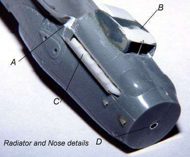 Another good friend from
Hyperscale, Bob Rinder pointed out that the
left side wing root fairing needs to be widened (A).
This wider fairing accommodates the DB 605D engine bearer. I accomplished
this with some epoxy putty. Bob also pointed out that the oil cooler fairing
is too shallow as it comes in the kit (B).
I studied several photos very closely and came to the conclusion that the
fairing is indeed too small, but not by much. I added a small bulge of
epoxy putty just under the lip of the intake. I carefully blended this
back and deepened the intake as the kits intake is noticeably too small.
I also added the reinforcing rod into the center of the intake and vacformed
the exhaust door. The exhaust stacks that come with the Cooper cockpit
are superb and are much better than the kits parts (C).
I carefully thinned down the kits exhaust shroud with a file. I used some
telescoping aluminum tubing to make a better prop mount (D). Another good friend from
Hyperscale, Bob Rinder pointed out that the
left side wing root fairing needs to be widened (A).
This wider fairing accommodates the DB 605D engine bearer. I accomplished
this with some epoxy putty. Bob also pointed out that the oil cooler fairing
is too shallow as it comes in the kit (B).
I studied several photos very closely and came to the conclusion that the
fairing is indeed too small, but not by much. I added a small bulge of
epoxy putty just under the lip of the intake. I carefully blended this
back and deepened the intake as the kits intake is noticeably too small.
I also added the reinforcing rod into the center of the intake and vacformed
the exhaust door. The exhaust stacks that come with the Cooper cockpit
are superb and are much better than the kits parts (C).
I carefully thinned down the kits exhaust shroud with a file. I used some
telescoping aluminum tubing to make a better prop mount (D).
Tail
Gear Bay
 The 109K featured a retractable tail wheel. The wheel assembly
itself was driven by a hydraulic ram that pulled the wheel to the closed
position or pushed it out to retract. The doors that covered the wheel
were spring loaded and would only close when the wheel assembly retracted
to the in-flight position. However many pictures of 109Ks show these doors
to be fully closed. This is because the wheels were often locked
in the down position and the doors where wired shut. The Squadron
109 part II book claims the 109K tail wheel doors would open briefly
to allow the tail wheel to retract. Careful study of the door closing
mechanism shows that this this is not possible. I am sure if these
doors are closed the wheel cannot retract because the door closing mechanism
is spring loaded to hold the doors open. Most of the pictures
I have seen of 109Ks show the doors closed so apparently it was a common
practice to lock the tail wheel down. I decided to open the doors on mine
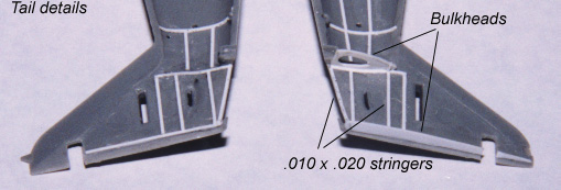
and thus needed to add some simple detail in the tail compartment. The
above photo shows the basic stingers and bulkheads I added. The layout
I used is largely speculative being based on some crude cutaway drawings
and educated guessing. The overall impression of detail is more accurate
than an empty bay. Later I added rudder linkages and an elevator
control rod. The 109K featured a retractable tail wheel. The wheel assembly
itself was driven by a hydraulic ram that pulled the wheel to the closed
position or pushed it out to retract. The doors that covered the wheel
were spring loaded and would only close when the wheel assembly retracted
to the in-flight position. However many pictures of 109Ks show these doors
to be fully closed. This is because the wheels were often locked
in the down position and the doors where wired shut. The Squadron
109 part II book claims the 109K tail wheel doors would open briefly
to allow the tail wheel to retract. Careful study of the door closing
mechanism shows that this this is not possible. I am sure if these
doors are closed the wheel cannot retract because the door closing mechanism
is spring loaded to hold the doors open. Most of the pictures
I have seen of 109Ks show the doors closed so apparently it was a common
practice to lock the tail wheel down. I decided to open the doors on mine
and thus needed to add some simple detail in the tail compartment. The
above photo shows the basic stingers and bulkheads I added. The layout
I used is largely speculative being based on some crude cutaway drawings
and educated guessing. The overall impression of detail is more accurate
than an empty bay. Later I added rudder linkages and an elevator
control rod.
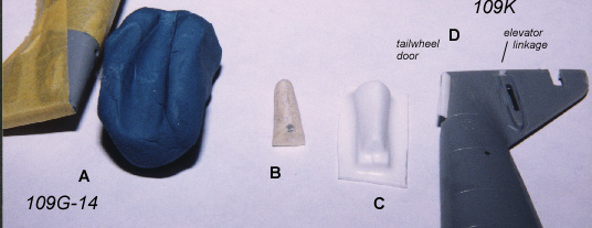
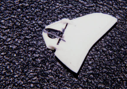
I decided I wanted to have scale thin tail gear doors. To accomplish
this I cut off the molded on kit doors. I took a blob of "klean klay" and
pressed it onto the tail section of my unbuilt Hasegawa Me-109G-14 (A).
I then filled the impression left in the clay with Resin (B).
This resin master was used to vacform some .020 plastic (C).
The doors where then cut from the formed plastic and glued to the fuselage
(D).
Once the fuselage halves were cemented together, I constructed
the tail wheel door closing mechanism (A).
I used a piece of a guitar string to make the spring located at the top
of the structure. I carved a thin trench in each of the horizontal stabs
and thinned the fuselage walls where the rudder attaches (B).
Improving
the Propeller
 Again, over on the Hyperscale discussion board, Peter Looper
noticed that the Hasegawa Kit props did not look right. He felt they did
not capture the broadness and were more pointed than those found in reference
pictures. I had not really noticed before but after looking at some
photos, I tended to agree with him. Again, over on the Hyperscale discussion board, Peter Looper
noticed that the Hasegawa Kit props did not look right. He felt they did
not capture the broadness and were more pointed than those found in reference
pictures. I had not really noticed before but after looking at some
photos, I tended to agree with him.
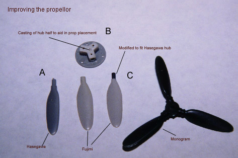
Eventually I decided to compare the
kit prop to a good photograph. The photo I used is found on page 53 of
the Squadron 109 part 2 (the top left corner - a 109K from 1/JG-77). I
used my scalecalc program to compare the length vs width dimension of this
real prop with those of the Hasegawa kit. The results seemed to show
that the kit pop (A) is to narrow by about
two scale inches (2/50 inches approx.) and hence pointed. This is
a small part and the missing 2/50" really throws the overall shape of the
kit part off causing it to be too pointed at the tip. This surprised
me because the kit prop perfectly matches the outline in the 1/48 scale
drawings found on page 90 of the Aerodetails 109G book. Apparently the
kit prop was based on these drawings - which I now believe have an inaccurate
prop profile. The Props from my Fujimi 109K (C)
kit seem to be more accurate than the Hasegawa kit props. I modified
a Fujimi prop by cutting it to the proper length and drilling a hole in
the base. I then inserted a plastic rod that matched the diameter of the
Hasegawa part to make the blades easy to install. I also made a casting
of the base of the spinner and trimmed the base part off leaving only the
prop lug. I glued this to the prop base. This leaves a nice hole to insert
the blades at a later time (B). Now I can
easily add my spinner spiral without having to worry about gluing the blades
on later. I also made a mold of the Fujimi blades so that I will have plenty
of them for future 109G-10 and 109K projects.
Landing
Gear
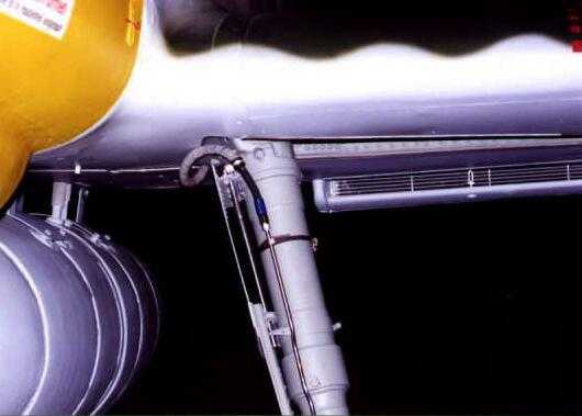
Here is a great shot of the upper section of a Me-109G-10s landing gear
and gear door assembly that was set to me by David Lake. As you can
see there is detail that is not represented well or is missing in the kit.
Vincent Kermorgant warns "This photo is very valuable for modellers but
the upper flexible cable route is incorrect as it should pass between the
back of the leg and the upper u/c door and not outside (for obvious reasons)
as pictured".
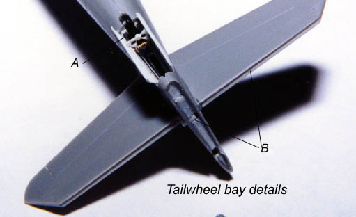
 First thing that needs to be replaced is the thick gear doors. I
used the photo etched doors that came with the old True Details etch set
that is designed for the Monogram 109G-10. This set only cost
about $3.50 and had very nicely done cooler parts and realistically thin
gear doors. Since this set is no longer available, I made a mold of the
lower gear door parts and cast them in resin (B).
The upper gear doors were cut from .005 sheet styrene and detailed with
sheet styrene and thin wire(A). The
brake line is .010 lead wire. Also visible is the open radiator inlet doors
(C).
First thing that needs to be replaced is the thick gear doors. I
used the photo etched doors that came with the old True Details etch set
that is designed for the Monogram 109G-10. This set only cost
about $3.50 and had very nicely done cooler parts and realistically thin
gear doors. Since this set is no longer available, I made a mold of the
lower gear door parts and cast them in resin (B).
The upper gear doors were cut from .005 sheet styrene and detailed with
sheet styrene and thin wire(A). The
brake line is .010 lead wire. Also visible is the open radiator inlet doors
(C).
Auxiliary
Doors
The auxiliary doors that come with the Cooper Details cockpit set
are much better than what the kit provides but still need some detail to
show where the device attaches to the wing. I scratchbuilt the triangular
mount that is visible just above the door. I then made the mechanism that
closes the door from lead sheeting.
"Messerschmitt Bf 109G" by Shigeru Nohara and Masatsugu
Shiwaku.
Published by Dia Nippon Kaiga Co., LTD ISBN not quoted.
"Messerschmitt Bf 109 in Action Part 2" by John R. Beaman
Jr.
Published by Squadron/Signal Publications INC. ISBN 0-89747-138-5.
Coming soon - the JAPO book!
Page Created 29 September 1999
Back to HyperScale Main Page
Back to Features Page
|  Home
| What's New |
Features |
Gallery |
Reviews |
Reference |
Forum |
Search
Home
| What's New |
Features |
Gallery |
Reviews |
Reference |
Forum |
Search