|
|
|
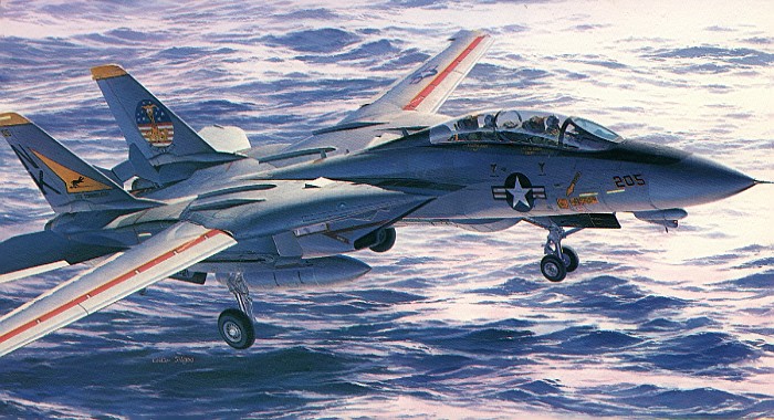
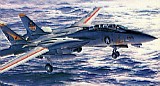
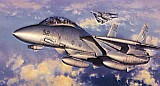
F-14A
Tomcat |

Hasegawa's
1/48 scale F-14A Tomcat and
Black
Box's F-14D replacement cockpit
are available online from Squadron.com
With apologies to Tom Cruise, the real star of the movie Top Gun is
the F-14 Tomcat. It is probably the most widely recognized and capable
Naval air superiority fighter of the modern era (my opinion, with
further apologies to all the Hornet lovers out there). With a design
dating back to the early Seventies, it remains one of the US Navy's
premier aircraft, even today.
The original Tomcat design was for a pure air defense fighter
employing long range Phoenix missiles to protect Carrier Groups from any
perceived aerial threat. Shorter range Sparrow and Sidewinder missiles
give the Tomcat close range armament. For the traditional dogfight, the
Tomcat is also equipped with the ubiquitous six-barrel Vulcan 20mm
rotary cannon. Later developments have introduced a reconnaissance role
to the Tomcat using the Tactical Air Reconnaissance Pod System (TARPS).
The most recent developments from the 1990s have now added ground attack
to the Tomcat's list of missions.
Hasegawa was quite late in releasing a Tomcat in 1/48th scale. Rumors
had been flying for years about them finally doing it. With a growing
line of F-4 Phantoms, A-7 Corsairs, and F-15 Eagles, it only made sense
that they would continue the line by including the F-14 Tomcat. Finally,
in the 1980s, a decade after the F-14 entered Fleet service, they
released a 1/48th scale kit.
This posting is another part in a multi-part posting on the Hasegawa
Tomcat. In this posting, I will describe the kits and discuss the issues
with constructing the kits. In future postings, I will highlight my
completed models of the Tomcat (I now have three) and discuss things
specific to each project.
The following are brief descriptions of a spattering of the earliest
releases that Hasegawa made on the F-14 Tomcat. This list is by no means
complete. I am only showing the roots of where the current Hasegawa
releases on the Tomcat are based. There have been numerous special
release kits with special decals for various aircraft, too numerous to
list them all. All these special release kits are just re-boxings of one
of the kits I list below. In some cases, like with the "Bombcat"
releases, the special release kits also include a few extra parts, but
the base kits remain unchanged.
 |
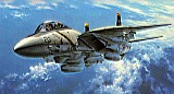
This is the original box art of the original Hasegawa F-14 Tomcat
kit, an F-14A (stock #07018 / P018). The kit was released in the
early to middle 1980s. It featured a slew of in-the-box options
(which I list later in this posting) and five different Pacific
Fleet marked aircraft in the decals (VF-21 and VF-154 in two
versions, each, and a VF-111 CAG). |
 |
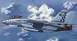
This is the box art of the second Hasegawa F-14 Tomcat kit, another
F-14A (stock #07019 / P019). This release was only a few weeks after
the first release and contained an identical kit to the first one.
Only the decals were different. This time the kit featured four
different Atlantic Fleet marked aircraft in the decals (VF-31,
VF-74, and VF-84 in two versions). |
 |
This is the box art of the third Hasegawa F-14 Tomcat kit, still
another F-14A (stock #07020 / P020). This release was only a few
months after the first two. This time the plastic components were
changed to represent an early block aircraft. The new components
replaced pieces from the earlier kit releases so that only an early
block aircraft can be built with this kit. To the current date, this
is the only Tomcat release with the components to build an early
block aircraft. The decals included both Atlantic and Pacific Fleet
markings (VF-1 CAG, VF-14, and VF-32 CAG). |
 |
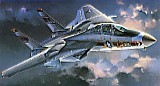
The F-14A+/B Tomcat was first released as a special release kit
(stock #51508 / SP008) with updated components to build an accurate
F-14A+/B Tomcat. The big change was the replacement of the P&W TF30
engine exhausts with the GE F110 engine exhausts. There were a few
other minor changes to the kit to complete the F-14A+/B. The decals
provided three low-vis aircraft (VX-4, VF-74, and VF-101). The box
art I have included here is actually the second release of an
F-14A+/B Tomcat as a standard stock kit (stock #07023 / P023). It
has the same plastic as the earlier special release kit, only with
new decals for three different aircraft (VF-74, VF-143, and VF-211
CAG). |
 |
As the F-14D was just hitting Fleet service, this kit was released.
This is a special release kit (stock #51544 / SP044) with updated
components to build an accurate F-14D Tomcat. Decals were provided
for two aircraft (VX-4 and VF-124). The kit was based on the earlier
F-14A+/B Tomcat kit releases. All the pieces needed to make the
F-14D were just added to the F-14A+/B kit without removing the
counterpart pieces. Knowing which pieces to mix and match allows the
construction of accurate F-14A+/B or F-14D models from this kit. To
date, no standard release kit of the F-14D has ever been made. There
have been multiple special release kits, though, providing a variety
of decals options. |
Hasegawa's 1/48 Scale
Tomcat Described
|
Do you want the short version or the long one? Anyone that has ever
built (or tried to build) one of the Hasegawa 1/48th scale Tomcat kits
can attest to there being lots you can say about them -- both good and
bad.
The short version is this -- on the good side, the Hasegawa 1/48th
scale Tomcats are the most detailed and accurate Tomcats of any kits on
the market today, bar none. This is a strong statement, but in my
opinion, it is true. On the bad side, the kits are quite a challenge to
build due to their many complexities and fit issues. Over the years, I
have actually not seen many of these kits finished. If you ever try to
build one, you will find out why many have never been finished. I would
bet most end up broken after being thrown against a wall. You really
have to want to complete the kit to put up with some of the issues it
presents.
If you do not care to read all the gory details about building these
kits, you can back out of this posting now and wait for my future
postings that will show my completed Tomcats. Otherwise, read on...
I acquired my first Hasegawa F-14 kit when it was originally released
in the middle 1980s. It cost a whopping $60 back then and is still
generally in the same ball park for its price today. On the heels of
Hasegawa's very well done F-4 Phantoms and A-7 Corsairs, I was sure that
the F-14 kit would not disappoint me and plunked down a half-week's
salary (at that time) without any hesitation. The kit turned out to be a
mixed blessing.
The original two releases of this kit provide all necessary
components to build any F-14A from the middle of the block 75 aircraft
(starting with BuNo 159421) up through the last F-14A to be produced (a
block 140 aircraft, BuNo 162711). Re-releases of the kit with different
parts allow the building of earlier F-14A Tomcats (prior to BuNo 159421)
as well as F-14A+/B/D Tomcats and "Bombcats". The only Tomcats that
Hasegawa does not provide a kit for are the twelve prototype /
pre-production aircraft (BuNo 157980 through 157991). Over the years, I
have acquired many of these kits (I have expensive taste). Most
everything I write here about constructing these kits applies to all the
kits, collectively.
The kits provide all of the following right in the box. This is quite
a list by any standard.
-
|
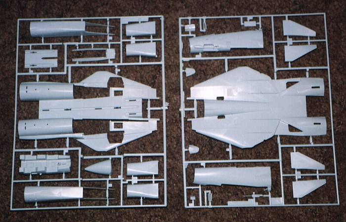
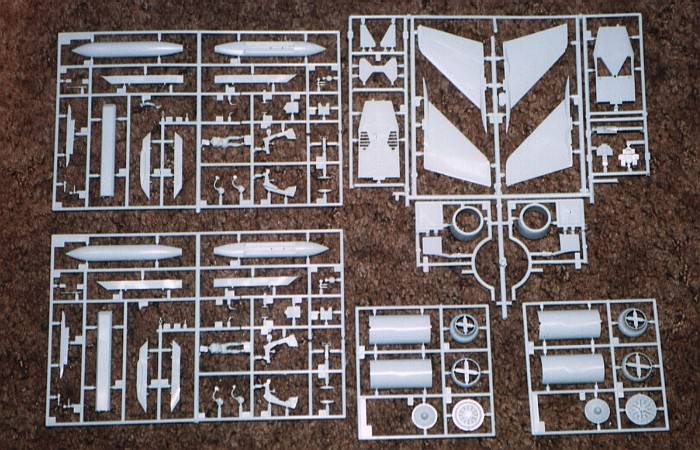
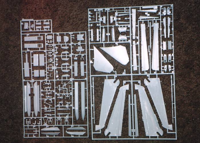
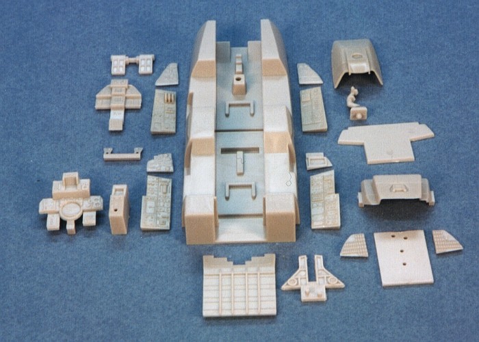
Hasegawa F-14 Tomcat
Parts Trees
Click
Thumbnails below to view larger images:
Parts Tree A and B
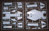
Parts Tree E, H and K
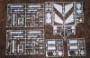
Parts Tree C and F
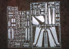
|
- Finely engraved panel lines throughout the entire kit.
- Raised cockpit detailing. Through the use of separate insert
pieces, Hasegawa provides accurate instrument panels for each of
their Tomcat kits. They just substitute different instrument panel
pieces.
- Optional position boarding ladder and steps. The ladder is
constructed using etched metal pieces to form the vertical sides.
There are no plastic pieces in the kit to replace these metal
ones, so you must use these etchings if you intend to construct
the model with its boarding ladder extended.
- Very well detailed landing gear. The main landing gear legs
are each composed of nine-pieces. The nose landing gear leg is
made up of thirteen-pieces including alternate pieces to allow you
to "kneel" the aircraft as it would be seen for a catapult launch.
The only things that the legs are missing are some wiring
harnesses. Apparently, Hasegawa intended to leave the wiring
harnesses up to the modeler to add as super-detailing items.
- White metal wheel hubs with rubber/vinyl tires. Included in
most of the kits are alternate wheels with varying spoke patterns
to model the different wheels used across a wide range of Tomcat
production blocks.
- Complete, fully detailed wheel wells.
- Optional position swing-wings. In support of the optional
position wings, Hasegawa provides alternate wing glove bladders.
These bladders inflate and deflate as the wings sweep forward and
back. They fill the slot that the wings swing in and out of, thus
preserving the aerodynamics of the fuselage. The alternate bladder
pieces allow for either fully inflated bladders with the wings all
the way forward or fully deflated bladders with the wings in
over-sweep (as they would be while parked on the carrier deck).
The kit allows for the wings to be positioned at any sweep angle,
but the bladders would need to be reworked to whatever partial
inflation level they should be to fill the wing slot.
- Optional position wing flaps and leading edge slats. Attaching
the flaps in the lowered position does require the positioning of
the wings to be fully forward.
- Optional position horizontal tails.
|
- Optional position speed brakes on the top and bottom of the
"beaver tail". The speed brake wells are appropriately detailed with
the correct ribbing and contours.
- Optional position tail hook. Actually, if you build it right, the
tail hook is functional and can be raised and lowered on the completed
model. I do not build my models as toys, so I glued the tail hook in
the position I wanted it (raised).
- Optional open and closed engine exhaust nozzles with complete
afterburner interiors all the way in to the flame holders and
turbines. Even in the F-14A+/B/D kits with the new engine exhaust
pieces, this option is still provided allowing the model to have
opened or closed engine exhaust nozzles.
- Full engine intake ducting back to a representation of the engine
faces. The contours of the ducting are not truely accurate, but to
have some form of ducting with an engine face is better than a blank
wall or, worse yet, an empty hole.
- A complete compliment of weapons pylons allowing most any
air-to-air weapons load to be modeled. Unfortunately, though, no
actual weapons are provided in the kit -- nothing -- not even a couple
Sidewinder missiles. This requires you to steal weapons from some
other kit or purchase some of the Hasegawa weapons sets. And, a gripe
of mine with the Hasegawa weapons sets is that the Phoenix missiles
are in the "smart bombs" set while all the other air-to-air missiles
are in a set of their own. This requires you to buy two weapons sets
to model a Tomcat with all three missile types on it, as if the Tomcat
kit did not cost enough already. A couple Hasegawa special release "Bombcat"
kits do include air-to-ground weapons, but no air-to-air weapons are
found in any of the kits to date.
- A TARPS reconnaissance pod. This is a big plus that Hasegawa could
have easily ignored. A full conversion to the TARPS configuration also
includes a fairing over of the middle front Sparrow missile well. The
later Hasegawa releases include the part to do this on the C tree
(part C51). The kit instruction sheets make no mention of this part or
where it goes, but that is its purpose.
- Open access doors with a representation of the 20mm Vulcan cannon
in the left nose. The real point here was that Hasegawa needed to
provide the gun covers as separate pieces because they are different
from one F-14 version to the next. The actual representation of the
20mm Vulcan cannon is rather poor, being nothing more than raised
detail inside the gun bay with no extra pieces to provide a true
representation of the 20mm Vulcan cannon. Several after-market
companies provide replacements of the gun bay interior that greatly
improve the look (if opening gun bays is your "thing").
- Finally, they provide what can only be termed as "extra pieces".
This includes all sorts of antennas and airframe variations that
provide the modeler with the ability to build most any Tomcat in
existence. Like the TARPS pod, these are a big plus that Hasegawa
could have easily ignored.
While this all sounds wonderful, it is not without a cost. There are
an extraordinary number of pieces in the kit. The original F-14A kits
contain 268 gray plastic, 16 clear plastic, 6 etched metal, 8 white
metal wheel hubs, and 4 vinyl tires. Quite a number of these pieces
(about 30) are the "extra pieces" I mention above that are optional
variations on the airframe allowing the modeler to build any specific
aircraft block number and weapons loading. Later releases of the kit
have the number of parts climbing even higher as in most cases, Hasegawa
added new options without removing the old ones. The high end of the
part count is found in one of the recent release of the F-14D Tomcat (in
overall black from VX-9). Because this kit includes trees of iron bombs
and everything needed to make a "Bombcat", the gray plastic parts top
out at nearly 500 pieces!
Building
Hasegawa's 1/48 Scale Tomcat
|
I was so excited by what I saw in the original Tomcat kit I purchased
that I started building it immediately. Then, I found some things with
the engineering of the kit that really disappointed me. Not that the
issues were insurmountable, but I had some preconceived ideas from what
the F-4 and A-7 kits were like. When the F-14 kit actually did have what
I considered "real" issues, I got disgusted and boxed the whole kit up,
putting it away in the closet. Note that this occurred in the middle
1980's where my Advanced Modelers Syndrome (AMS) was at its worst. It
was easy to convince me back then that any kit was too much trouble. The
disappointment has lingered, though, and is the biggest reason it has
taken me until now to finally build the kit. I will relate the issues I
ran into as I walk through the construction sequence for the kit.
The troubles I ran into with the kit relate in many ways to the
complexities introduced by all the pieces. The main trouble spots are
only in a few specific places. In fairness to Hasegawa, I have to state
that later releases of these kits have had the moldings reworked to help
alleviate some of the issues that I outline here. Depending on which kit
is being built, it may or may not have the reworked moldings. The
original kits (stock#07018 and #07019) seem to be the most likely kits
to not be reworked. Every other release of the kit I have checked has
the reworked moldings.
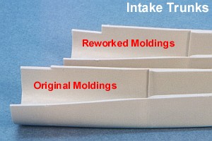 To
tell if a kit is a reworked one, check the engine intake pieces. If
there is a deep half-inch notch cut out of the inside corners of these
pieces, the kit is a reworked one.
To
tell if a kit is a reworked one, check the engine intake pieces. If
there is a deep half-inch notch cut out of the inside corners of these
pieces, the kit is a reworked one.
Like most kits, the construction starts in the cockpit. The basic kit
cockpit is "generic" so that it is reusable between all the various kit
releases. The main cockpit tub has no detailing. Into the tub are
installed all the specific detail pieces to provide the correct details
for the specific Tomcat version being built. I found that some of the
detail pieces did not fit as well as they could.
The front cockpit side consoles are a sixteenth of an inch too small
for the space on the cockpit tub that they fit into. The intention is
that they are attached flush to the rear wall, leaving a slot at their
front ends. Then, the left and right instrument sub-panels are supposed
to slip down into these slots. There are two issues here. The slots are
not wide enough to fit the sub-panels, and the sub-panels have raised
details all the way to their edges. Some of the details on the lower
section of the sub-panels get covered up when the they are slipped into
the slots in front of the side consoles. I thinned the sub-panels by
sanding down the backing so they would fit into the slots in front of
the side consoles and just accepted that some detailing was getting
covered up as I slid them into place.
The rear bulkheads of both cockpits cause trouble. In the front
cockpit, the piece does not want to slide down into place inside the
cockpit tub. Be aware, also, that the beveling on the edges dictates
that one side is the front and the other side is the back on this piece.
If you insert it backwards, a noticeable gap appears at the base of the
part. I filed down the sides of this piece to get it to slide into
place.
The issue with the rear cockpit bulkhead is one of not having enough
substance. The bulkhead builds up in three pieces that do not actually
touch when they are installed in the cockpit tub. This provides a place
to see into the fuselage behind the rear cockpit. I solved this by
adding some sheet styrene backings onto the pieces.
Lastly, when attaching the rear main instrument panel and instrument
hood into the cockpit, the front of the hood does not touch the top of
the front cockpit bulkhead, leaving a sixteenth of an inch gap. I added
some strip styrene to the top of the front cockpit bulkhead to fill this
void.
When all these fit issues were addressed, then it was time to address
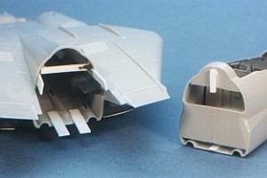
the details that Hasegawa missed in the cockpits. I purchased the Eduard
photo-etchings set for the Hasegawa Tomcat (stock#48-155) to obtain lots
of details for the cockpits. Included in the Eduard set are really nice
representations of the cockpit canopy sills.
The next items on my list of cockpit improvements were the cockpit
side walls. Hasegawa molds nothing into the inside of the fuselage
halves to represent the assorted side wall details found in the Tomcat.
I was preparing to scratch build these items when Black Box released
their F-14A Tomcat cockpit for the Hasegawa kit. The Black Box set fixes
all the issues I outline above by replacing the entire cockpit. It also
provides side wall details for the cockpits. I simply discarded the
modified kit pieces and counted myself lucky for not investing too much
time on the cockpit issues.
For a full review of the Black Box F-14 Tomcat cockpit and its
integration into the Hasegawa Tomcat kit, see my other reviews: "Tomcat
Cockpit" and "Tomcat Cockpit Painting".
Following the completion of the cockpit, I assembled the forward
fuselage. In the original release kits, before the moldings were
reworked, the kit cockpit does not fit inside fuselage sides real well.
I needed to cut off the sides of the cockpit tub to gain clearance so
the fuselage would fit together. In the kits with reworked moldings, the
cockpit fits inside the fuselage without any issue. When I swapped to
using Black Box cockpit, I did not have to worry any more about it.
After dealing with the cockpit and the forward fuselage, the rear
fuselage is a snap. In one evening, I cut, cleaned, trimmed, and
assembled the entire rear fuselage (without the engine intakes). A
little care was needed to get the "beaver tail" to fit smoothly without
too much of a joint line, but this was workable without using filler.
The main wheel well interior pieces proved to be a bit of a puzzle.
After tinkering with them for almost an hour, I finally relised that
they are intentionally too tall. The top edge of them comes to a shape
beveled point. When joining the upper and lower fuselage halves, this
point is crushed over the raised details on the inside of the upper
fuselage. This is an odd choice by Hasegawa to get a tight fit, but it
works. I just needed to accept this was the way it was intended to work.
The worst fitting pieces in the entire kit were found when I started
work on the engine intakes. The cockpit issues are a "cake walk"
compared to the engine intakes.
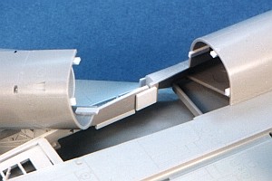 The
intake trunk pieces just do not match the contours of the fuselage. They
also lack positive alignment points to assist in getting them to fit the
lower fuselage. The fit issues are compounded if you do not get the main
wheel well pieces to sit just right. My recommendation is to use as
little glue as possible to build and install the main wheel wells. As
none of them are load-bearing in the kit, this is fine. That way, you
can adjust the placement of the wheel well pieces to accomodate the
engine intake trunking.
The
intake trunk pieces just do not match the contours of the fuselage. They
also lack positive alignment points to assist in getting them to fit the
lower fuselage. The fit issues are compounded if you do not get the main
wheel well pieces to sit just right. My recommendation is to use as
little glue as possible to build and install the main wheel wells. As
none of them are load-bearing in the kit, this is fine. That way, you
can adjust the placement of the wheel well pieces to accomodate the
engine intake trunking.
I carefully fit and adjusted the fit of the intake trunk pieces to
make them line up on the fuselage. Then, I added some strip styrene
locators to assist me with the alignment at the rear end of the pieces.
Finally, I adjusted the fit and location of the main wheel well backing
pieces (kit parts C15 and C16) so that they would not interfere with the
intakes. The engine intake issues are sort of addressed in the kit
releases with reworked moldings. The moldings changed, but most of the
fit problems are still there.
In addition to the poor fit of the intake trunks to the lower
fuselage, the fit of the intake ducting inside the trunks is pretty bad.
I needed to use more than a little filler to blend the interior of the
intake trunks into the intake ducting pieces. The entire area should be
smooth, but the kit has loads of knockout pin locations and rough
plastic. While a lip is molded into the trunk for the ducting to fit
into, the ducting does not reach it.
My final intakes, after sanding the filler, were not really correct
(still), but they were better looking than the way the stock kit
provided them. I figured that the view afforded in the front of the
intakes would be limited enough to hide any remaining shape issues. I
was proved right after the intake trunks were attached.
 Before
attaching the intake trunks to the lower fuselage, I painted their
insides gloss white. After this dried, I masked and painted the
camouflage color of the outer portion of the inner intake. I had no
specific pictures of the aircraft I was building that showed the intake
interiors. Hence, I masked the most typical paint line I have seen
inside Tomcat intakes. Check your references when doing this masking as
the line can change from aircraft to aircraft.
Before
attaching the intake trunks to the lower fuselage, I painted their
insides gloss white. After this dried, I masked and painted the
camouflage color of the outer portion of the inner intake. I had no
specific pictures of the aircraft I was building that showed the intake
interiors. Hence, I masked the most typical paint line I have seen
inside Tomcat intakes. Check your references when doing this masking as
the line can change from aircraft to aircraft.
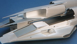
During the process to attach the intake trunks to the lower fuselage,
you also attach the intake variable geometry ramps (kit parts F10, F11,
F12, and F13). If attached the way they are provided in the kit, these
ramps are positioned like they would be in supersonic flight. As this
configuration is never seen on the ground when the aircraft is parked, I
modified the installation of the ramps to correct their placement.
I deleted the actuating rods for the forward ramps (kit pieces H6)
and removed all of the raised details on the backs of the forward ramps.
This allows the forward ramps to be attached in a highest, flush
position. Then, I cut all but a sixteenth of an inch of the oleo
extension off of the rear ramp actuators (kit pieces H7). This
effectively halved the length of these actuators. This allows the rear
ramps to be attached in corresponding higher positions to match the new
positions of the forward ramps. This revised ramp configuration better
captures the look of the intakes when the aircraft is parked on the
flight line.
After attaching the intake trunks to the lower fuselage, I found that
another place to work out was the area just under the upper lip of the
intake. The intake trunks have pointed forward extensions that should
transition smoothly into the lower edge of the intake lip. This was not
happening. I used still more filler to shape and blend the pointed
forward tips of the intake trunk into the lower side of the intake lip.
If I ever build another of these Tomcat kits, I will strongly
consider using intake covers on the model to hide all these intake
issues.
 With
the intakes completed and fully attached, I attached the forward
fuselage to the rear fuselage. The joint between the forward and rear
fuselage did not align well. The cross-section shapes of the two
fuselage sections are not the same. I used a heavy styrene strip to
widen the upper portion of the rear fuselage opening. This helped the
forward and rear fuselage shapes to match each other better.
With
the intakes completed and fully attached, I attached the forward
fuselage to the rear fuselage. The joint between the forward and rear
fuselage did not align well. The cross-section shapes of the two
fuselage sections are not the same. I used a heavy styrene strip to
widen the upper portion of the rear fuselage opening. This helped the
forward and rear fuselage shapes to match each other better.
By this time, I was getting used to applying liberal amounts of
filler to this kit. I applied some more filler and sanded it out to
smooth the fuselage joint. I also needed to reinforce the inner
structure of the fuselage joint. I had placed a lot of lead shot in the
nose area of the model to guarantee the it would sit correctly on its
landing gear. This made me fear that the nose section would get broken
off if I was not careful. The reinforcing gave me some peace of mind.
At this point I was holding a nearly completed fuselage that was
starting to really look like a Tomcat. I thought the big issues were
finally past, but I had one more to go -- the wings. The wing problems
relate mostly to the wing flaps and the pieces that go into the wing
flap construction to support the lowered wing flaps.
To build the model with the flaps retracted (up), things fit pretty
much as advertised. All that is needed is to thin the trailing edge of
the upper wing piece, and the flap slides in with very little extra
effort. Not readily apparent in the instructions is that the "eyelid"
doors (kit parts C1 and C8) are discarded when the flaps are up.
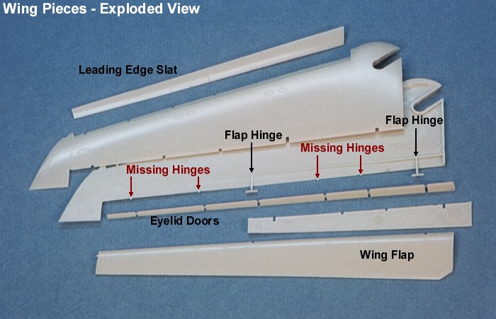
Building the model with the flaps positioned down is where the fun
starts. I found the flap pieces do not fit the wings as well as they
could. Troubles start with the "eyelid" doors. First off, the
instruction sheet has these parts labeled backwards. Put C1 where the
instructions tell you to put C8, and vice versa. Even when these pieces
are on the correct side, they are still too thick to fit into the thin
space between the upper and lower wing pieces. I ended up separating
these doors into three pieces each, cutting and filing away some of
their backing portions, to get them to go into place.
 Then,
Hasegawa only provides two hinge/actuator points to connect the flap
to the wing. There should be six. There are locator points on the
flaps and wings for all six hinge/actuator points, but these are
some parts that Hasegawa apparently neglected to include in the kit.
I nipped off the two provided hinge points, as they are a little too
long and incorrectly shaped. Then, I built up all six
hinge/actuators using strip styrene. Then,
Hasegawa only provides two hinge/actuator points to connect the flap
to the wing. There should be six. There are locator points on the
flaps and wings for all six hinge/actuator points, but these are
some parts that Hasegawa apparently neglected to include in the kit.
I nipped off the two provided hinge points, as they are a little too
long and incorrectly shaped. Then, I built up all six
hinge/actuators using strip styrene.
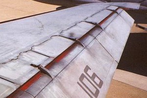
A friend I met on the Internet (Danny Deters) sent me some great
detail pictures of the lowered flaps on a Tomcat. Studying these
detail pictures helped considerably with the process to build the
hinge/actuators. With Danny's permission, I have included some of
his pictures below: |
|
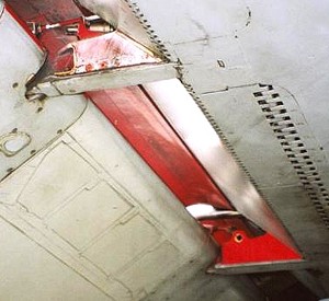
Inboard, Underside |
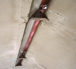
Outboard,
Underside |
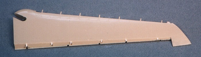
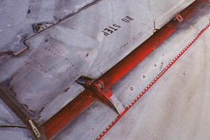
I was still unhappy with the look of the flaps. After some extended
investigation, I found out why. Hasegawa molds the wing flaps,
themselves, incorrectly. They are too big! Hasegawa molded their pieces
on the assumption that the flaps are a fowler style flap that slides
back as it comes down. The truth is that the flaps are a slotted type
that merely pivots down with the "eyelid" doors retracting to reveal a
slot between the wing and the flap. No sliding back occurs. The bottom
line is that the Hasegawa flaps are too long in their cord by about an
eighth of an inch, the width of the "eyelid" doors.
After some investigation on how best to fix the problem, I initially
came to the conclusion that fixing the kit pieces would be harder than
just creating new flaps from scratch. Then I looked more into the
scratch building effort and decided I really was not up for that,
either. After further scrutiny of the kit pieces, I found that simply
cutting off the leading edges of the pieces and filing them back to air
foil shapes would work. So, that is what I did.
I cut the kit wing flaps following the scribe line that defines the
"eyelid" doors (when the flap is retracted). Then I filed the leading
edges of the parts to re-create the proper airfoil shape. I fixed the
scribing that was lost during this process. I machined in the attachment
points for the hinges that attach the flap to the wing. Lastly, I added
the bumps on the upper flap surfaces that attach the actuators to the
flap.
 |
|
Inboard, Topside
|
Outboard, Topside
|
 |
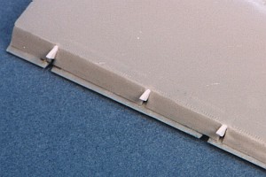
The last error by Hasegawa on the wing flaps involves the location of
the flap actuators and the hinges points. Each actuator rod should be
centered over a hinge point. Only two of the six actuator points align
with the hinges. The others are skewed left or right by up to a quarter
of an inch. I chose to not try to fix this alignment issue because it
would involve rebuilding the (at the time I learned this information)
already constructed "eyelid" doors and re-scribing the piano hinges for
the "eyelid" doors. Perhaps on a future build of the kit I will tackle
fixing the actuator locations.
The Hasegawa wing flaps always looked somehow wrong to me. After
discovering and fixing most all of these wing flap problems, I was much
happier with the look of the dropped flaps. I considered raising the
wing spoilers while I was working on the wing, but decided against it. I
had my hands full with just fixing the incorrect flaps. Like the flap
actuators, perhaps on a future build of the kit I will tackle raising
the spoilers.
I left the wings loose (unglued) in the fuselages of my completed
models. The fit is tight enough on the wings to hold them in place
without glue. This way I can remove the wings for transporting the
models.
By now I was getting really tired of the model (again), so it was
fortunate that I had finally reached the end of the big problems. The
engine exhausts were no real trouble. Note that the engine exhaust
nozzle adapters have a definite left and right side. I test fitted these
between the left and right sides until I got it right, then added glue.
Note that on F-14A+/B and D Tomcats (with the GE engines) the engine
exhaust nozzle adapters should have all their scribing filled and sanded
smooth. This area on the real aircraft is some high-tech fiber surface
with no panel lines running through it. All it has is a series of
attachment screws running along the edges.
A very typical parked stance of the F-14A engine exhausts has one
side wide open and the other side fully closed. What happens is this.
While taxiing, both engines are fully open. When the first engine is
shut down, the aircraft is still powered by the second engine. The
flight control computer cycles the shut down engine exhaust fully closed
in a attempt to increase thrust. When the second engine is shut down, no
power is available any more and the second engine remains fully open.
The operating mechanism on the F-14A engine exhausts is not effected by
gravity, so the exhausts remain in whatever position they are in at shut
down.
If both engines are fully open (on a parked F-14A), it means they
were shut down pretty much at the same time. It is rare to find both
engines fully closed on the ground.
On the F-14A+/B and D Tomcat, the typical parked stance of the engine
exhausts is to have both exhausts wide open. The same operational
behavior occurs to the engine exhausts that occurs on the F-14A. The
difference is that the operating mechanism of the engine exhausts on the
F-14A+/B and D is very much effected by gravity. Within minutes after
shut down, the engine exhausts are pulled open by gravity.
The landing gear constructed and plugged into the wheel wells with no
issue. I added wiring and plumbing to the landing gear legs using fine
wire. The rubber/vinyl tires provided by Hasegawa are both good and bad.
With time, they squash on the model while it sits on your display
shelves so that they create convincing looking weighted tires. Then,
with more time, they start to decompose and leave oily spots on your
display shelves. Finally, they start to crack and fall apart. I learned
this from using the rubber/vinyl tires in the high-grade F-4 Phantom
kits. Hence, I replaced the F-14 wheels and tires with resin items
available from Cutting Edge.
I added the various antennae and little details at the end of the
project, just before declaring myself done. Even these were not without
some headaches.
The arresting hook is about a quarter of an inch too long. This
causes it to hang out beyond the beaver tail. It should be even with the
end of the beaver tail. I cut off the end of the hook, removed about a
quarter of an inch from the end of the center rod portion, and
re-attached the hook tip.
The COM antennae along the spine do not fit the locator holes on the
fuselage. I filled the kit provided holes and redrilled some of my own.
While I was at it, I scratch built new antennae from .020 inch sheet
styrene (cut to size to match the kit pieces).
The nose tip pitot part does not really fit the hole on the tip of
the nose cone. Also, it is too long. I took the same approach here as I
did on the spine COM antennae and scratch built a new pitot with brass
wire and the "pitot-less" nose tip in the kit. Then, I filled the hole
on the nose tip and redrilled a new hole to match the thickness of the
brass wire.
The boarding ladder uses etched metal pieces to construct its
vertical sides. These are too thin looking when built, so I laminated
.015 inch sheet styrene onto them and trimmed them to size. Using
appropriate sized drill bits, I drilled the litening holes into the
sides where they existed in the etched piece. This thicker construction
looked more appropriate to what I saw in pictures of a real Tomcat
boarding ladder.
The mounting holes for the horizontal tails were too large. The tails
just hung in them. After contemplating several not-too-easy options, I
decided to take a "cheap" approach that worked. I applied a bead of
super glue inside the holes and let it dry. This reduced the hole size
just enough so that the tails fit snuggly. I needed no glue to secure
them. This makes them more survivable over the upcoming years on my
display shelves. Since they are not glued, they will just move if (when)
I bump them instead of breaking.
The instruction sheet has parts #L10 and #L11 (the wingtip navigation
lights) backwards. I painted mine on the sprue using the instruction
sheet to tell me which part would be which color (clear red or clear
green). When I went to attach them to the wingtips, they did not work on
the sides that I painted them for. The correct placement, for the record
-- #L10 is the left (red), #L11 is the right (green). I stripped the
clear paint off using an old bottle of Polly-S paint and decal remover.
Then painted them again in the correct colors before attaching them to
the wings.
In reality, none of the trouble areas I ran into are impossible to
fix. That I fixed them proves this point. They only take a some extra
time and a little tinkering with the kit's engineering. For the kit's
cost, though, these areas should work right out of the box. Hence, back
in the 1980s when I first started the kit, my AMS took over and I just
socked the kit away.
It is a shame that I had to wait so long to get over the disappointed
feelings so that I could finally get up the courage to complete this
monster. Compared to the state-of-the-art technology found in most of
the recent Hasegawa and Tamiya releases, this is not an easy kit to
build. But, it is not all that bad. It is better than some old Airfix
kits I have worked on. The completed kit is quite pleasing to look at
and worth the effort to complete.
I got so into these Tomcat kits when I was finally building them
(after fifteen years of feeling disappointed with the kit) that I built
three kits all at the same time. Look for the three different Tomcats to
get posted separately in future postings.
Go to Part One - Building the Black Box Cockpit
Go
to Part Two - Painting the Cockpit for Effect
Go to Part Four - Painting an NSAWC Tomcat
Model, Description and Images Copyright ©
2001 by David Aungst
Page Created 03 August, 2001 Home
| What's New |
Features |
Gallery |
Reviews |
Reference |
Forum |
Search
Home
| What's New |
Features |
Gallery |
Reviews |
Reference |
Forum |
Search